Propulsive anti-torque system for rotorcraft

a technology of rotorcraft and torque, applied in the field of rotorcraft, can solve the problems of increasing the power required with increasing speed, reducing the productivity of hammers, and reducing the efficiency of rotorcraft, so as to improve the productivity of rotorcra

Active Publication Date: 2010-06-08
TEXTRON INNOVATIONS
View PDF15 Cites 47 Cited by
  • Summary
  • Abstract
  • Description
  • Claims
  • Application Information

AI Technical Summary

Benefits of technology

[0005]Therefore, it is an object of the present invention to provide a rotorcraft having a propulsive anti-torque system that improves the productivity of the rotorcraft while addressing the limitations of the classical helicopter configuration.
[0007]These objects are achieved by providing a rotorcraft having an enhanced helicopter configuration in which a simple wing and a propulsive anti-torque system are combined. The propulsive anti-torque system includes an anti-torque thruster system in which a variable pitch fan is installed internal to the tail boom of the rotorcraft and an anti-torque thruster nozzle is mounted at the extremity of the tail boom. The fan is driven directly from the main rotor drive via a short shaft. The configuration and location of the fan allows the primary exhaust from the engine to be mixed with the air flow from the fan. The mixed air flow from the fan and the engine passes through the tail boom and out the thruster nozzle. All embodiments of the rotorcraft of the present invention may be configured for either manned or unmanned operation.
[0008]The present invention provides significant advantages, including: (1) the cruising speed of the rotorcraft can be increased by 30-40 knots; (2) blade loading and flapping are significantly reduced; (3) the margins for hub and control loads are improved; (4) the quality of the ride at high speeds is significantly improved; (5) the noise level in hover and overflight is significantly reduced; and (6) system complexity is greatly reduced; (7) the infrared (IR) signature of the rotorcraft is significantly reduced, because the primary engine exhaust is highly diluted when mixed with the air flow from the fan; (8) the acoustic signature of the rotorcraft is greatly reduced, because both the primary engine and the propulsive anti-torque system are internal to the tail boom of the rotorcraft; (9) the rotorcraft is significantly safer for personnel during ground operations, because both the primary engine and the propulsive anti-torque system are internal to the tail boom of the vehicle, thereby eliminating the possibilities of exposure to hot exhaust gasses or tail rotor strikes; (10) anti-torque thrust is provided without the cost, weight, and complexity of a tail-rotor type device or a thrust type device that uses a fan driven by a secondary drive system; and (11).

Problems solved by technology

With the classical helicopter configuration, there are certain fundamental limitations that hamper improvements in productivity, including: retreating blade stall, blade loading, advancing blade tip Mach number, and the large increases in power that are required with increased speed.
These physical limitations contribute to increased vibration, with its resulting poor ride quality and reduced component life.
In addition, these physical limitations lead to increased size, which increases the ultimate cost of the helicopter due to the synergistic growth of the configuration when the helicopter is designed to address these limitations.
Incorporation of these approaches, due to their increased complexity and weight, reduces the economic load carrying capability of the helicopter and raises questions as to the safety of operation of the helicopter and its long term reliability.

Method used


Image

  • Propulsive anti-torque system for rotorcraft
  • Propulsive anti-torque system for rotorcraft
  • Propulsive anti-torque system for rotorcraft

Examples


Embodiment Construction

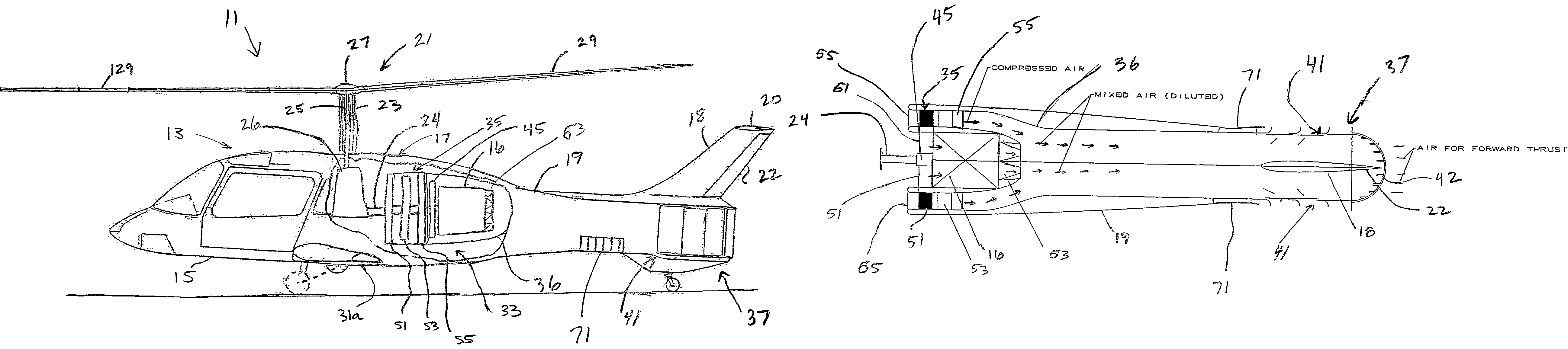
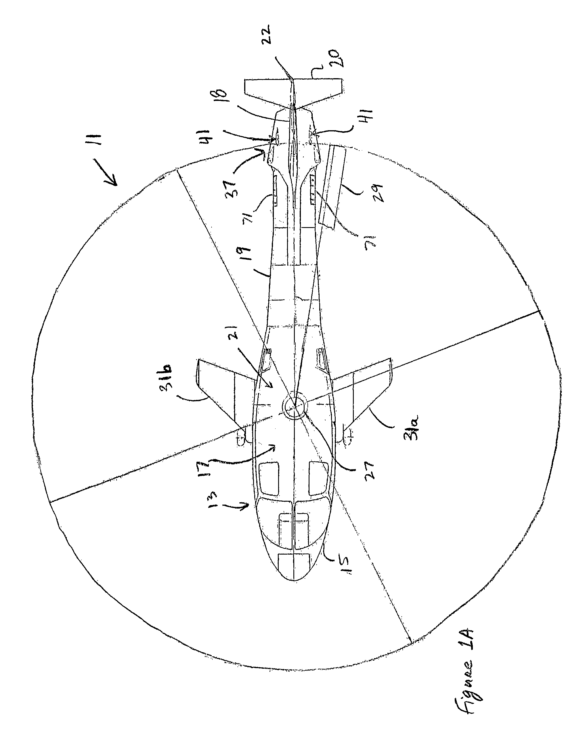
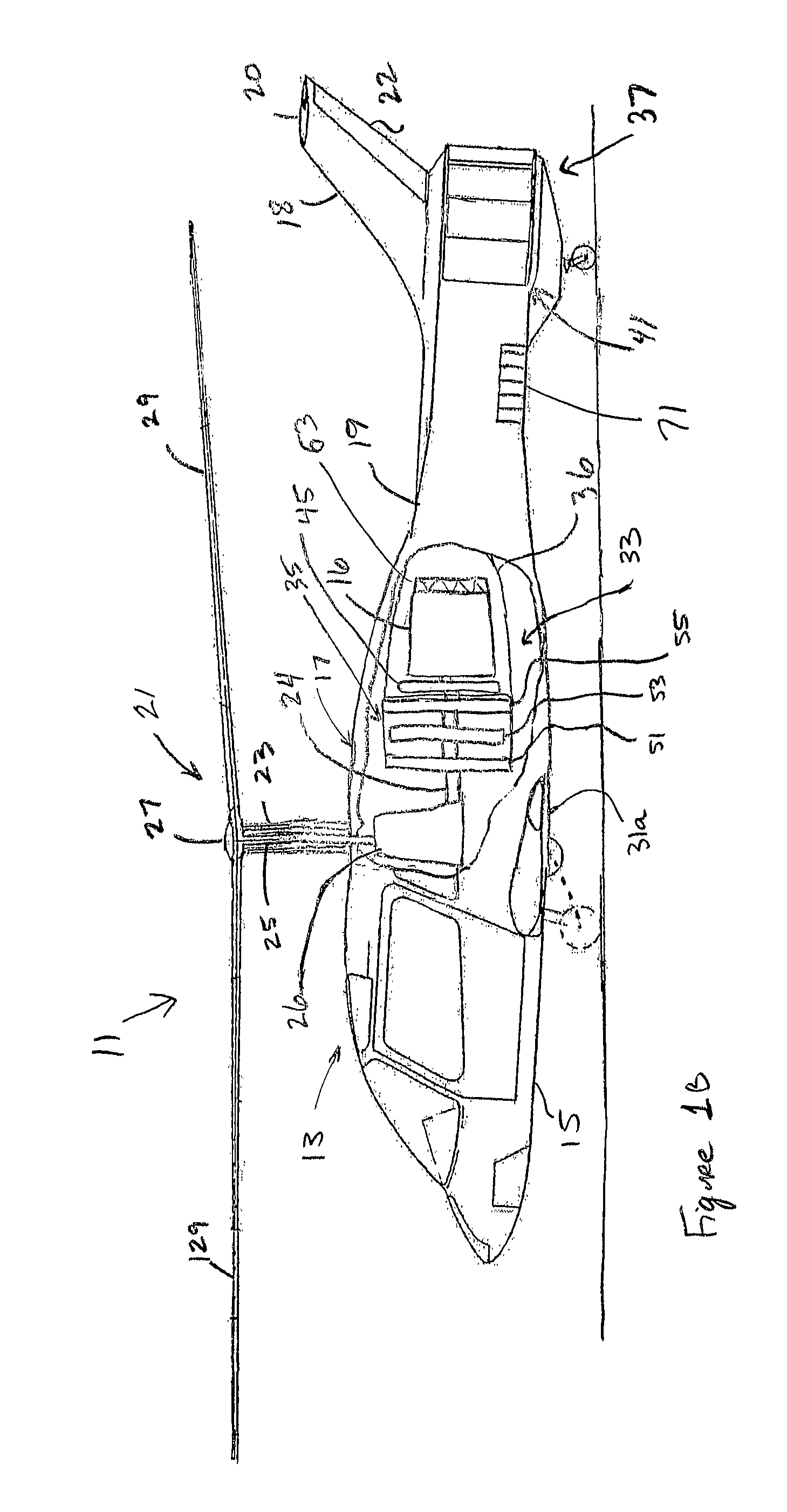
[0017]The present invention represents a unique combination of lift compounding and propulsion compounding to create a small rotorcraft that can travel at very high speeds. The lift compounding is provided by a small wing, and the propulsion compounding is provided by a pneumatic propulsive anti-torque system. Although the present invention will be described herein with respect to helicopters, it will be appreciated that the present invention may be utilized on a wide variety of rotorcraft.

[0018]Referring to FIGS. 1A and 1B in the drawings, the preferred embodiment of a helicopter 11 according to the present invention is illustrated. FIG. 1A is top view of helicopter 11, and FIG. 1B is a cut-away side view of helicopter 11. Helicopter 11 includes an airframe 13 having a cabin portion 15, an upper canopy 17, a tail boom 19, a vertical tail fin 18, a horizontal stabilizer 20, and a controllable rudder 22. Helicopter 11 is powered by a primary turboshaft engine 16 carried within tail b...


PUM


Abstract

A rotorcraft having an enhanced configuration in which a simple wing and a propulsive anti-torque system are combined is disclosed. The propulsive anti-torque system includes an anti-torque thruster system in which a variable pitch fan is installed internal to the tail boom of the rotorcraft and an anti-torque thruster nozzle is mounted at the extremity of the tail boom. The fan is driven directly from the main rotor drive. The configuration and location of the fan allows the primary exhaust from the engine to be mixed with the compressed air flow from the fan. The mixed air flow from the fan and the engine passes through the tail boom and out the thruster nozzle.

Description

TECHNICAL FIELD[0001]The present invention relates to rotorcraft. In particular, the present invention relates to propulsive anti-torque systems for rotorcraft.DESCRIPTION OF THE PRIOR ART[0002]To make a meaningful improvement in the productivity of conventional helicopters, an increase in the cruising speed of about 30% is required, and the improvement must be achieved within certain noise and ride quality constraints. Historically, improvements in helicopter productivity have been, at best, only incremental. The primary reason for this is the classical helicopter configuration. With the classical helicopter configuration, there are certain fundamental limitations that hamper improvements in productivity, including: retreating blade stall, blade loading, advancing blade tip Mach number, and the large increases in power that are required with increased speed. These physical limitations contribute to increased vibration, with its resulting poor ride quality and reduced component life...

Claims


Application Information

Patent Timeline
Patent Type & Authority Patents(United States)
IPC IPC(8): B64C27/82
CPCB64C27/82B64C2027/8245B64C2027/8236
Inventor SMITH, DUDLEY E.JOINER, WALTER C.MADEJ, PAUL J.HOLLIMON, CHARLES L.ROBERTSON, DANIEL B.
Owner TEXTRON INNOVATIONS
Why Eureka
Try Eureka