
Brush holder

a brush holder and holder technology, applied in the field of brush holders, can solve the problems of relatively high cost of producing the brush holder as a whole, relatively high cost of producing the brush holder, and the roller spring means and the bearing means, and achieve the effect of improving the lateral support of the carbon brush

Inactive Publication Date: 2008-05-15
HILTI AG
View PDF0 Cites 1 Cited by
  • Summary
  • Abstract
  • Description
  • Claims
  • Application Information

AI Technical Summary

Benefits of technology

The present invention provides a brush holder with improved lateral support for the carbon brush using simple spring means. The brush holder includes a contact spring and a supporting spring that generates a supporting pressure independently. The taper formed by the guide surface and the adjacent guide side ensures stable support of the carbon brush even after a long period of operation and compensates for lateral wear. The guide is delimited exclusively by the inclined guide surface and the supporting spring, which makes possible a uniform application of pressure to the carbon brush and prevents tilting of the carbon brush even with strong vibrations. The supporting spring has a clamping portion and an application portion that contacts the carbon brush over a length amounting to at least 80% of the length of the guide surface along the guide axis, preventing formation of areas with increased wear to a great extent. The invention reduces production costs and prevents tilting of the carbon brush.

Problems solved by technology

The drawback of the known brush holder consists in that the scroll spring means and the bearing means, which is required for the latter on the brush holder, are relatively costly to produce.
Accordingly, the costs of producing the brush holder as a whole is relatively high.
In addition, the supporting pressure that can be generated by the scroll spring means is relatively small so that strong vibrations can lead to a tilting of the carbon brush in the carbon holder and, therefore, to accelerated wear in some areas.

Method used


Image

  • Brush holder
  • Brush holder
  • Brush holder

Examples


Embodiment Construction

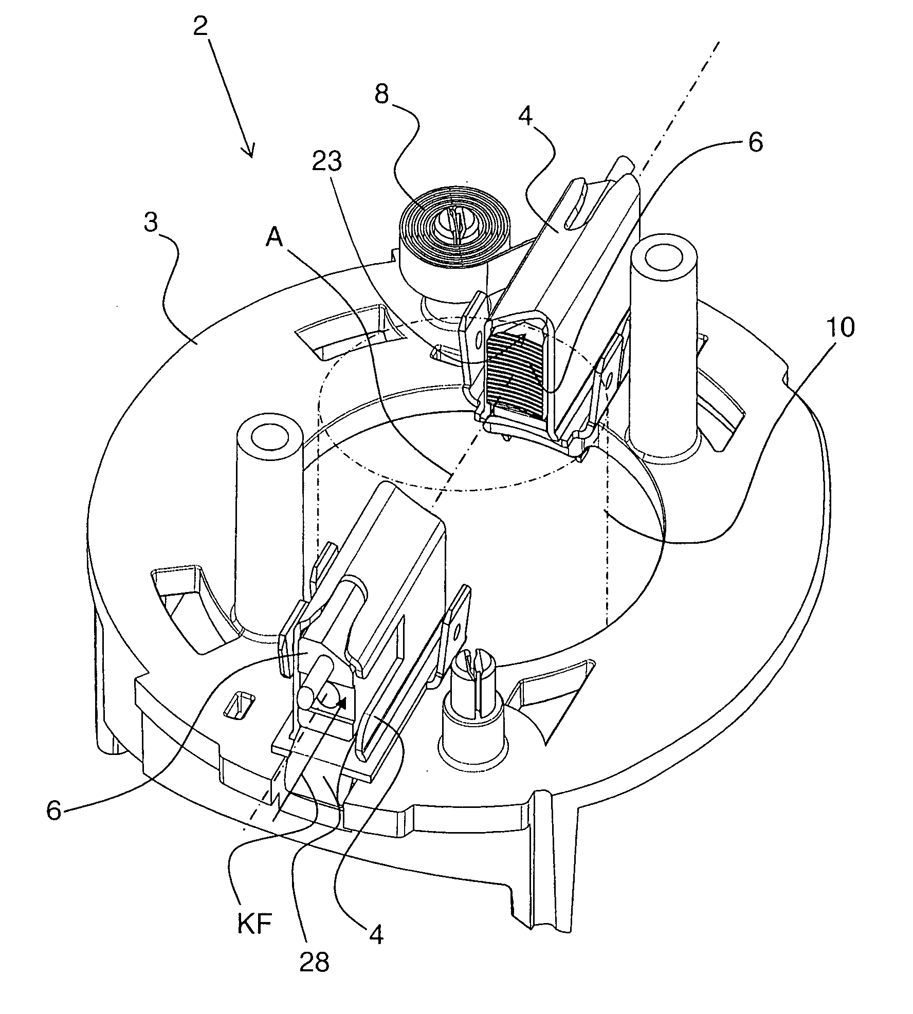
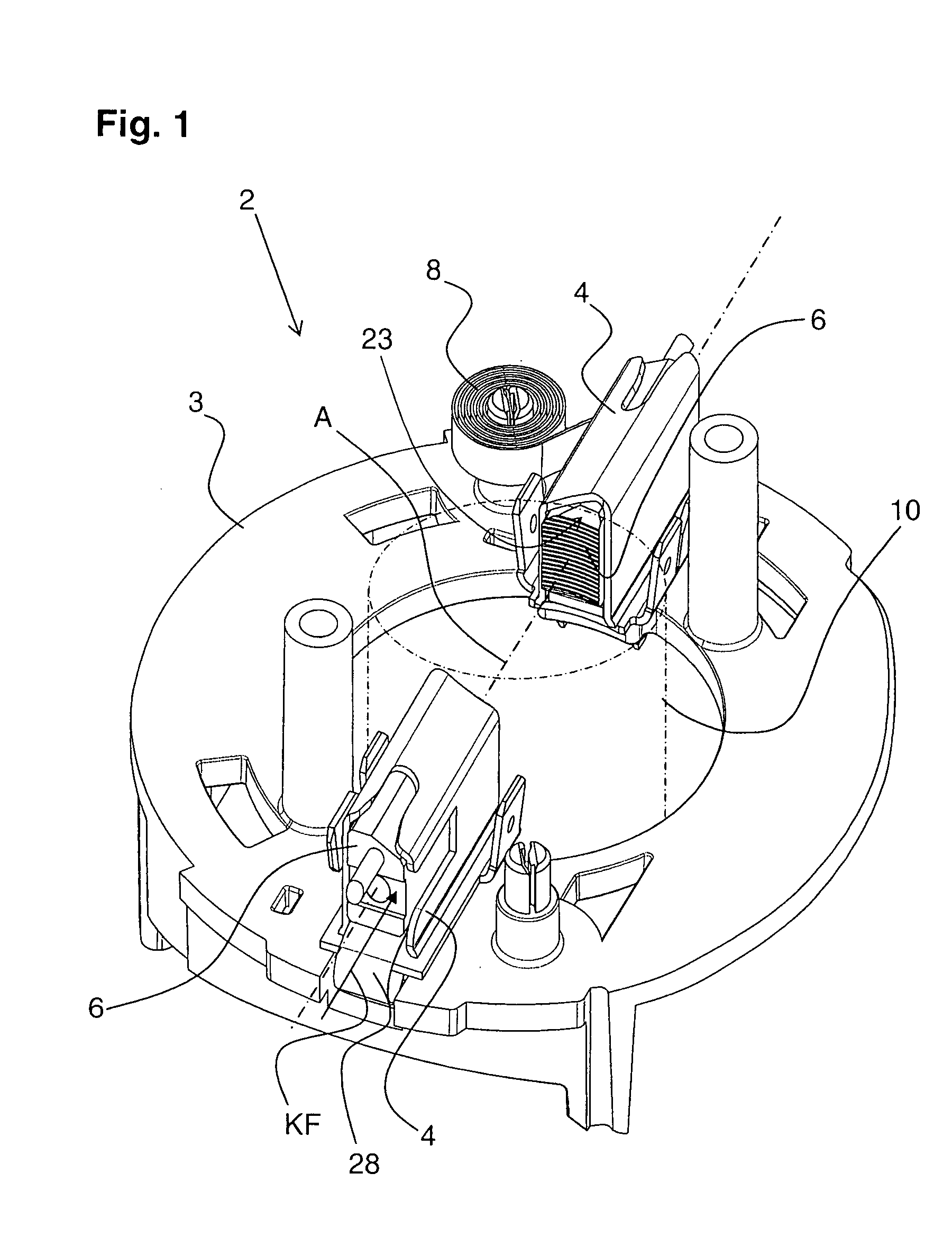
[0021]FIG. 1 shows a brush holder 2, particularly for a hand-held power tool, not shown, with a substantially ring-shaped carrier 3 that supports two carbon holders 4. Carbon brushes 6 are guided in these carbon holders 4, with each carbon brush 6 being biased against a commutator 10 by a contact spring force KF generated by a contact spring 8. The contact springs 8 are formed, for example, as coil springs. For the sake of clarity, only one contact spring 8 is shown.

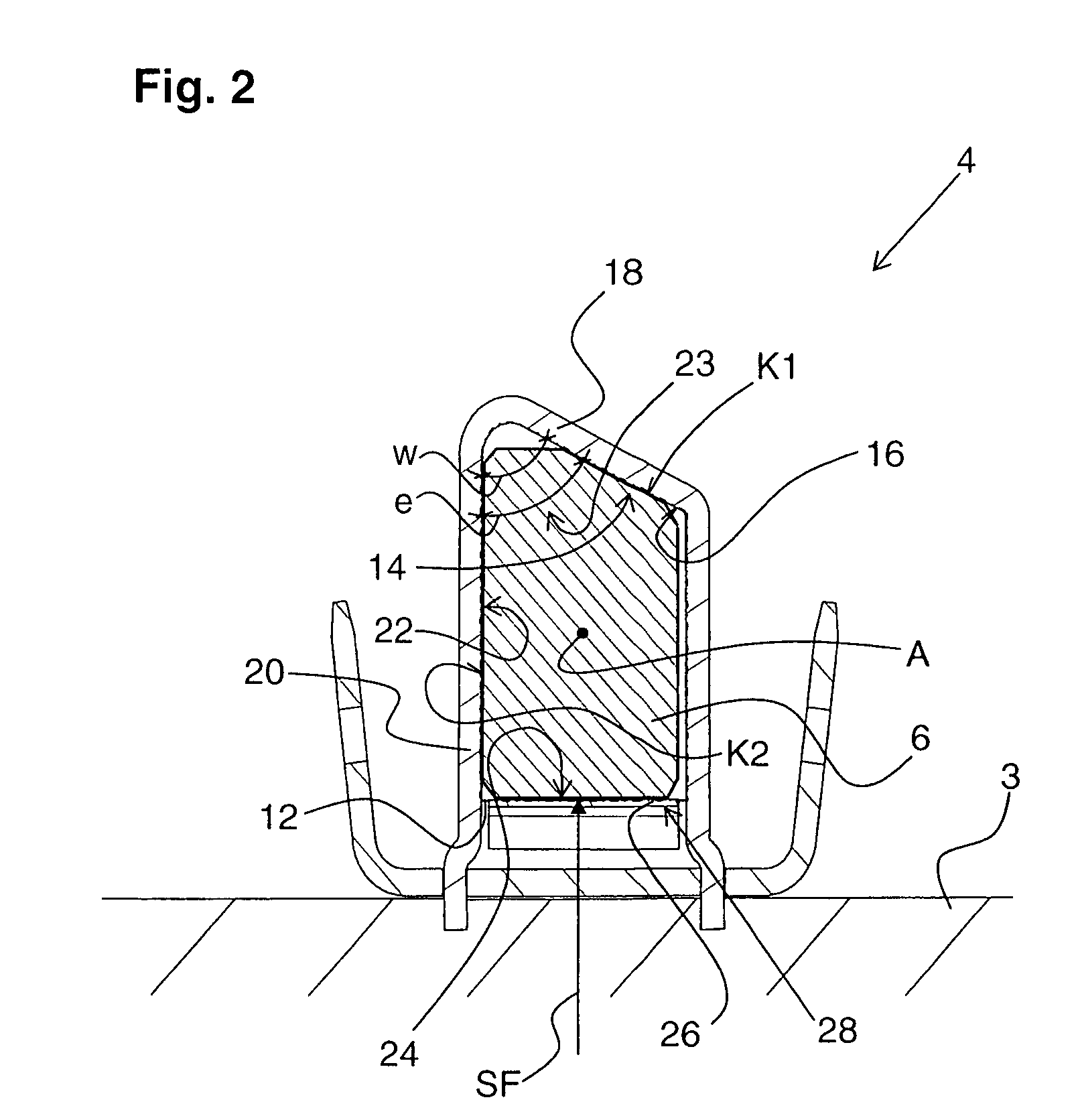
[0022] To guide a respective carbon brush 6, each carbon holder 4 forms a substantially four-sided guide 12 along a guide axis A, as can be seen particularly from FIG. 2. A first guide side 14 remote from the carrier 3 is substantially formed by a guide surface 16 of a holder wall 18 which is arranged at an inclination to a second guide side 22 formed by a holder wall 20, and encloses therewith an acute angle w. Accordingly, the guide surface 16 together with the second guide surface 22, forms a taper 23 directed transv...


PUM


Abstract

A brush holder (2) has a carbon holder (4) which forms a guide (12) for a carbon brush (6) and at which there is provided a spring arrangement that applies a contact spring force (KF) to the carbon brush (6) along the guide (12) and, at the same time, presses the carbon brush (6) into a taper (23) of the guide (12) with a supporting spring force (SF), with the spring arrangement having a contact spring (8) for generating the contact spring force (KF) and a supporting spring (28) which is separate from the latter and which generates the supporting spring force (SF).

Description

BACKGROUND OF THE INVENTION [0001] 1. Field of the Invention [0002] The invention is directed to a brush holder having a carbon holder which forms a guide for carbon brushes, spring means provided at the carbon holder for applying a contact spring force to the carbon brush along a guide axis of the guide. At the same time, the spring means biases the carbon brush transverse to the guide axis into a taper of the guide with a supporting spring force, and the carbon brush has a corresponding taper which cooperates with the taper of the guide. [0003] 2. Description of the Prior Art [0004] In brush holders of the type mentioned above, the carbon brushes are held in the carbon holders in a relatively stable manner. The spring means ensures that the carbon brushes are biased in direction of a commutator and that the carbon brushes are supported in the carbon holders laterally so as to be substantially free of play. Possible wear at the side surfaces of the carbon brushes is compensated in ...

Claims


Application Information

Patent Timeline
Patent Type & Authority Applications(United States)
IPC IPC(8): H01R39/44H01R39/41
CPCH01R39/415
Inventor TUSSING, TORSTEN
Owner HILTI AG
Learn More