A brick kiln automatic stacking machine

A kind of stacking machine and automatic technology, which is applied in the direction of cranes, trolley cranes, object stacking, etc., can solve the problems of brick falling, strong rotational inertia force, and affecting the quality of bricks, so as to prevent extrusion damage and strengthen The effect of positioning accuracy and improving stacking efficiency

Active Publication Date: 2019-03-26
天长市天釜新型建材有限公司
View PDF5 Cites 0 Cited by
  • Summary
  • Abstract
  • Description
  • Claims
  • Application Information

AI Technical Summary

Problems solved by technology

[0006] 1. The gripper of the coder is connected to the motor reducer through the lifting belt, so that the grabbed bricks can be lifted upwards, but because the clamping force of the gripper of the coder cannot be adjusted, especially when clamping bricks of different sizes , it is easy to cause damage to the adobe falling and extrusion damage, which reduces the quality and efficiency of the adobe;
[0007] 2. When stacking adobes in two layers, the gripper of the adobe stacker grabs a large number of adobes and is heavy. Its rotation is difficult to control, and the rotational inertia force is strong, which leads to poor positioning of adobes and reduces the efficiency of adobes stacking. ;
[0008] 3. When the walking trolley stops, the impact force is relatively large, so that the adobes held by the gripper of the adobe coder are prone to fall, which affects the quality of the adobes

Method used


Image

  • A brick kiln automatic stacking machine
  • A brick kiln automatic stacking machine
  • A brick kiln automatic stacking machine

Examples


Embodiment 1

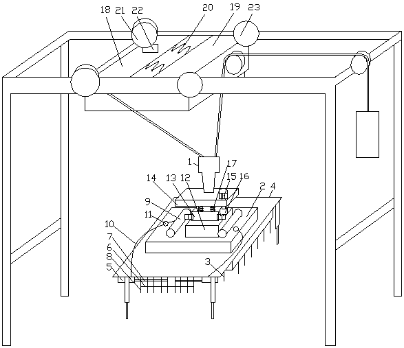
[0039] See figure 1 , A brick kiln automatic blanking machine, comprising a frame, a counterweight, a blank clamping device, a lifting device 1 and a walking device. The walking device is slidably connected to the beam of the frame. The blank clamping device includes a chuck 2 and a clamp 3. The bottom of the chuck 2 is connected with a telescopic frame 4, and the clamp 3 is fixed on the inner wall of the telescopic frame 4. The clamp 3 is composed of a cylinder 5, a connecting rod 6, a telescopic rod 7 and at least two side-by-side splints 8. The cylinder 5 is fixed on On the telescopic frame 4, the telescopic rod 7 is connected with the piston rod of the cylinder 5, the splint 8 passes through the telescopic rod 7, the two adjacent splints 8 are connected by the connecting rod to form a linkage, and the chuck 2 is connected with a gas tank 9. The cylinder 5 communicates with the gas storage tank 9 through the gas distribution pipe 10, the air intake end of the gas distribution...

Embodiment 2

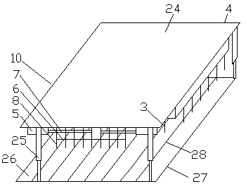
[0042] See figure 1 with figure 2 , A brick kiln automatic blanking machine, comprising a frame, a counterweight, a blank clamping device, a lifting device 1 and a walking device. The walking device is slidably connected to the beam of the frame. The blank clamping device includes a chuck 2 and a clamp 3. The bottom of the chuck 2 is connected with a telescopic frame 4, and the clamp 3 is fixed on the inner wall of the telescopic frame 4. The clamp 3 is composed of a cylinder 5, a connecting rod 6, a telescopic rod 7 and at least two side-by-side splints 8. The cylinder 5 is fixed on On the telescopic frame 4, the telescopic rod 7 is connected with the piston rod of the cylinder 5, the splint 8 passes through the telescopic rod 7, the two adjacent splints 8 are connected by the connecting rod to form a linkage, and the chuck 2 is connected with a gas tank 9. The cylinder 5 communicates with the gas storage tank 9 through the gas distribution pipe 10, the air intake end of the g...

Embodiment 3

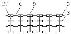
[0047] See Figure 1-Figure 3 , A brick kiln automatic blanking machine, comprising a frame, a counterweight, a blank clamping device, a lifting device 1 and a walking device. The walking device is slidably connected to the beam of the frame. The blank clamping device includes a chuck 2 and a clamp 3. The bottom of the chuck 2 is connected with a telescopic frame 4, and the clamp 3 is fixed on the inner wall of the telescopic frame 4. The clamp 3 is composed of a cylinder 5, a connecting rod 6, a telescopic rod 7 and at least two side-by-side splints 8. The cylinder 5 is fixed on On the telescopic frame 4, the telescopic rod 7 is connected with the piston rod of the cylinder 5, the splint 8 passes through the telescopic rod 7, the two adjacent splints 8 are connected by the connecting rod to form a linkage, and the chuck 2 is connected with a gas tank 9. The cylinder 5 communicates with the gas storage tank 9 through the gas distribution pipe 10, the air intake end of the gas di...


PUM


Abstract

The invention discloses an automatic green brick stacking machine of a brick kiln. The machine is characterized in that a telescoping frame is connected to the bottom part of a chuck, wherein a clamp is fixed to the inner wall of the telescoping frame; a cylinder is fixed to the telescoping frame; a clamping plate passes through a telescoping rod; the cylinder communicates with an air storing tank through an air distributing tube; the air distributing tube is connected with an air pressure regulator; a base on which a gyring support is arranged is connected to the top part of the chuck; a pressing plate on which a speed reducer is arranged is rotatably connected to the gyring support; a connecting gear is connected to an output shaft of the speed reducer; a spring column is arranged between the pressing plate and the gyring support; the pressing plate is connected with a lifting device; a moving device comprises a first frame plate, a second frame plate and a tension spring column; a driving wheel which is driven through a servo motor is arranged on the first frame plate; a driven wheel is arranged on the second frame plate. With the adoption of the machine, each green brick can be successfully clamped; the chuck can self-adaptively adjust the inertia force during rotating; when pausing, the moving device can self-adaptively buffer the inertia impacting force, so that the stability of the green brick in moving can be improved, and as a result, the green brick stacking efficiency can be improved.

Description

Technical field [0001] The invention relates to the technical field of sintered brick machinery and equipment, and in particular to an automatic blanking machine suitable for quickly laying bricks in a brick kiln. Background technique [0002] Automatic blank stacking machine is a kind of mechanical equipment that automatically divides, grabs, moves and stacks bricks in sequence. [0003] The automatic blanking machine is mainly composed of a blank separating device, a blank clamping device, a walking device, a lifting device, a rotating device, a hydraulic system, and an electrical system. Among them, the lifting device is connected with the walking device and the rotating device, and the rotating device is connected with the blank clamping device. connection. Compared with the manual stacking method, it has the advantages of high production efficiency and good brick stacking quality. When the automatic stacking machine is working, after the cutting machine pushes the cut bricks...

Claims


Application Information

Patent Timeline
Patent Type & Authority Patents(China)
IPC IPC(8): B65G57/02B65G57/20B66C19/00
CPCB65G57/02B65G57/20B66C19/00
Inventor 何娟石一利
Owner 天长市天釜新型建材有限公司
Why Eureka
Try Eureka