Clamping device for flexible substrate and method for fabricating the same

a flexible substrate and clamping technology, which is applied in the direction of sewing machine elements, workpiece holders, manufacturing tools, etc., can solve the problems of inability of the machine producing the size of the display device originally on the mobile communication device may not be large enough to display all the increased quantity of data, and the inability of the machine to produce the tft display device to clamp a flexible substrate to achieve the effect of smoothly clamping

Inactive Publication Date: 2007-05-31
IND TECH RES INST
View PDF12 Cites 5 Cited by
  • Summary
  • Abstract
  • Description
  • Claims
  • Application Information

AI Technical Summary

Benefits of technology

[0007] Accordingly, the present invention is to provide a clamping device for a flexible substrate that the flexible substrate can be clamped smoothly.
[0008] The present invention is to provide a clamping device for a flexible substrate whose fabrication process is compatible with the process for fabricating a thin film transistor (TFT). Furthermore, the clamping device can withstand a high temperature and is chemically stable, tough and heat resistant.
[0009] The present invention is to provide a clamping device for a flexible substrate that facilitates production processing.
[0019] In the clamping device of the present invention, the fixed positioning assembly can provide a means of positioning and the curved extending arms of the movable positioning assemblies can provide an spring force in different directions. Hence, the relative position between the hole body and the positioning hole can be micro-adjusted so that the positioning hole of the movable positioning assembly and the positioning hole of the flexible substrate can align. Consequently, when the flexible substrate is positioned on the carrier board of this clamping device and the dowel pins are inserted into the positioning holes of the hold bodies, the flexible substrate is smoothly flattened out.
[0020] The clamping device in the present invention for clamping a flexible substrate has special properties including the capacity to withstand a high temperature, chemically stable, tough and heat resistant. Moreover, the processing method is compatible to the method of fabricating thin film transistor (TFT) display device so that it can be applied using the existing equipment to produce roll up type flexible display device. In other words, considerable equipment cost can be saved through the method of the present invention.

Problems solved by technology

However, with the gradual increase in functions, the display device originally on the mobile communication device may not be large enough to display all the increased quantity of data.
In general, the cost of producing the components of a display device is relatively high.
However, the machine for producing the TFT display device is incapable of clamping a flexible substrate.
Yet, the gluing method of fixing the flexible substrate has many drawbacks.
First, the planarity of the attached flexible substrate is not so good.
Furthermore, many production processes such as chemical evaporation deposition, thermal evaporation deposition, plasma etching, photolithographic process or the spin-coat process frequently cause the peeling of the flexible substrate due to heat or chemical attack of the adhesive agent.
Once the flexible substrate has peeled off from the place of attachment, subsequently processes cannot proceed.

Method used


Image

  • Clamping device for flexible substrate and method for fabricating the same
  • Clamping device for flexible substrate and method for fabricating the same
  • Clamping device for flexible substrate and method for fabricating the same

Examples


Embodiment Construction

[0033] Reference will now be made in detail to the present preferred embodiments of the invention, examples of which are illustrated in the accompanying drawings. Wherever possible, the same reference numbers are used in the drawings and the description to refer to the same or like parts.

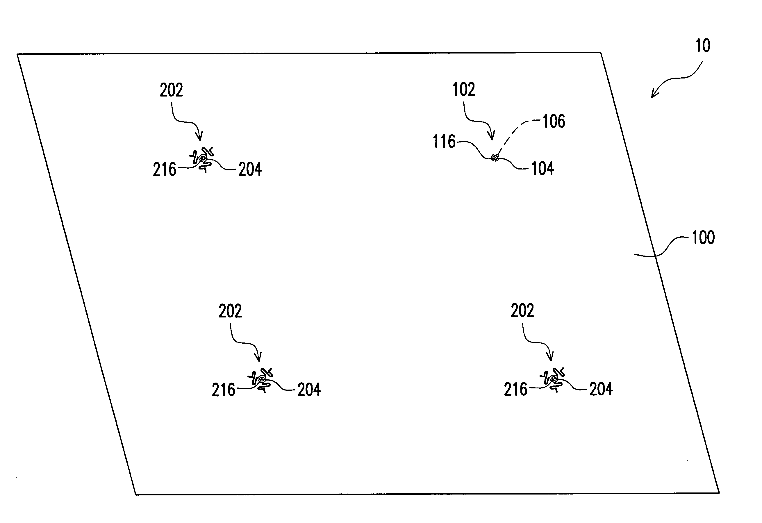
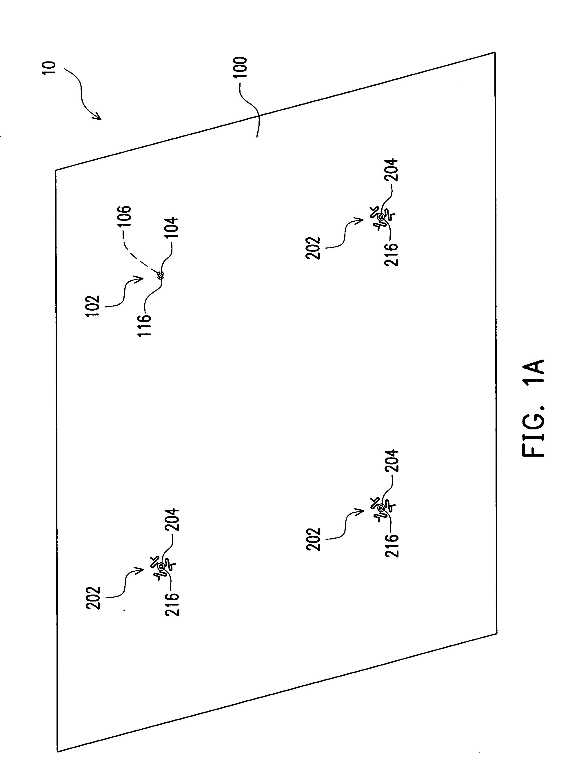
[0034]FIG. 1A is a top view of a clamping device for a flexible substrate according to one embodiment of the present invention. As shown in FIG. 1A, the clamping device 10 for a flexible substrate in the present invention includes a carrier board 100. The carrier board 100 has a fixed positioning assembly 102 and a plurality of movable positioning assemblies 202. The fixed positioning assembly 102 and the movable positioning assemblies 202 are disposed in locations that correspond to a plurality of through holes in the flexible substrate. When the clamping device 10 is used to grip the flexible substrate, the fixed positioning assembly 102 serves as a positioning point. Meanwhile, the movable posit...


PUM

PropertyMeasurementUnit
flexibleaaaaaaaaaa
shapeaaaaaaaaaa
temperatureaaaaaaaaaa

Abstract

A clamping device for a flexible substrate is provided. The clamping device includes a carrier board. The carrier board has a fixed positioning assembly and a plurality of movable positioning assemblies. The fixed positioning assembly and the movable positioning assemblies are disposed in locations that almost correspond to a plurality of through holes on the flexible substrate. The fixed positioning assembly includes a hole body with a positioning hole and a dowel pin. Each movable positioning assembly includes a hole body with a positioning hole, a plurality of curved extending arms and a dowel pin. Each curved extending arm is connected to the hole body and the carrier board and the dowel pin is inserted into the positioning hole.

Description

CROSS-REFERENCE TO RELATED APPLICATION [0001] This application claims the priority benefit of Taiwan application serial no. 94141429, filed on Nov. 25, 2005. All disclosure of the Taiwan application is incorporated herein by reference. BACKGROUND OF THE INVENTION [0002] 1. Field of the Invention [0003] The present invention relates to a clamping device and manufacturing method thereof. More particularly, the present invention relates to a clamping device for a flexible substrate and method of fabricating the same. [0004] 2. Description of the Related Art [0005] Due to the continuous progress on the technology of integrated circuit process and an increasing need for mobile communication, personal mobile communication equipments have continuously integrate a lot of function for entertainment or personal information management (PIM). However, with the gradual increase in functions, the display device originally on the mobile communication device may not be large enough to display all t...

Claims


Application Information

Patent Timeline
Patent Type & Authority Applications(United States)
IPC IPC(8): H01S4/00
CPCH01L21/683H01L21/687Y10S269/903Y10T29/5313Y10T29/53196Y10T29/49947Y10T29/49826Y10T29/49208Y10T29/53178Y10T29/49222Y10T29/49998Y10T29/53174Y10T29/49002H05K13/0069
Inventor WU, CHIN-JYITSAI, CHEN-DERTU, YUN-CHUANWONG, TE-CHI
Owner IND TECH RES INST
Why Eureka
Try Eureka