Work fixture for cylindrical optical element

A technology of optical components and fixtures, which is applied in the direction of manufacturing tools, workpiece clamping devices, etc., can solve the problems of component deformation and difficult clamping, and achieve the effect of improving stability and avoiding looseness

Pending Publication Date: 2019-02-19
XI AN JIAOTONG UNIV
View PDF0 Cites 4 Cited by
  • Summary
  • Abstract
  • Description
  • Claims
  • Application Information

AI Technical Summary

Problems solved by technology

For the processing of optical components with holes in the center, the clamping method is generally used for installation, but the components with holes in the center are not easy to clamp due to the size of the workpiece and the weakness in the middle, and it is easy to cause deformation of the components

Method used


Image

  • Work fixture for cylindrical optical element
  • Work fixture for cylindrical optical element
  • Work fixture for cylindrical optical element

Examples


Embodiment Construction

[0029] The present invention is described in further detail below in conjunction with accompanying drawing:

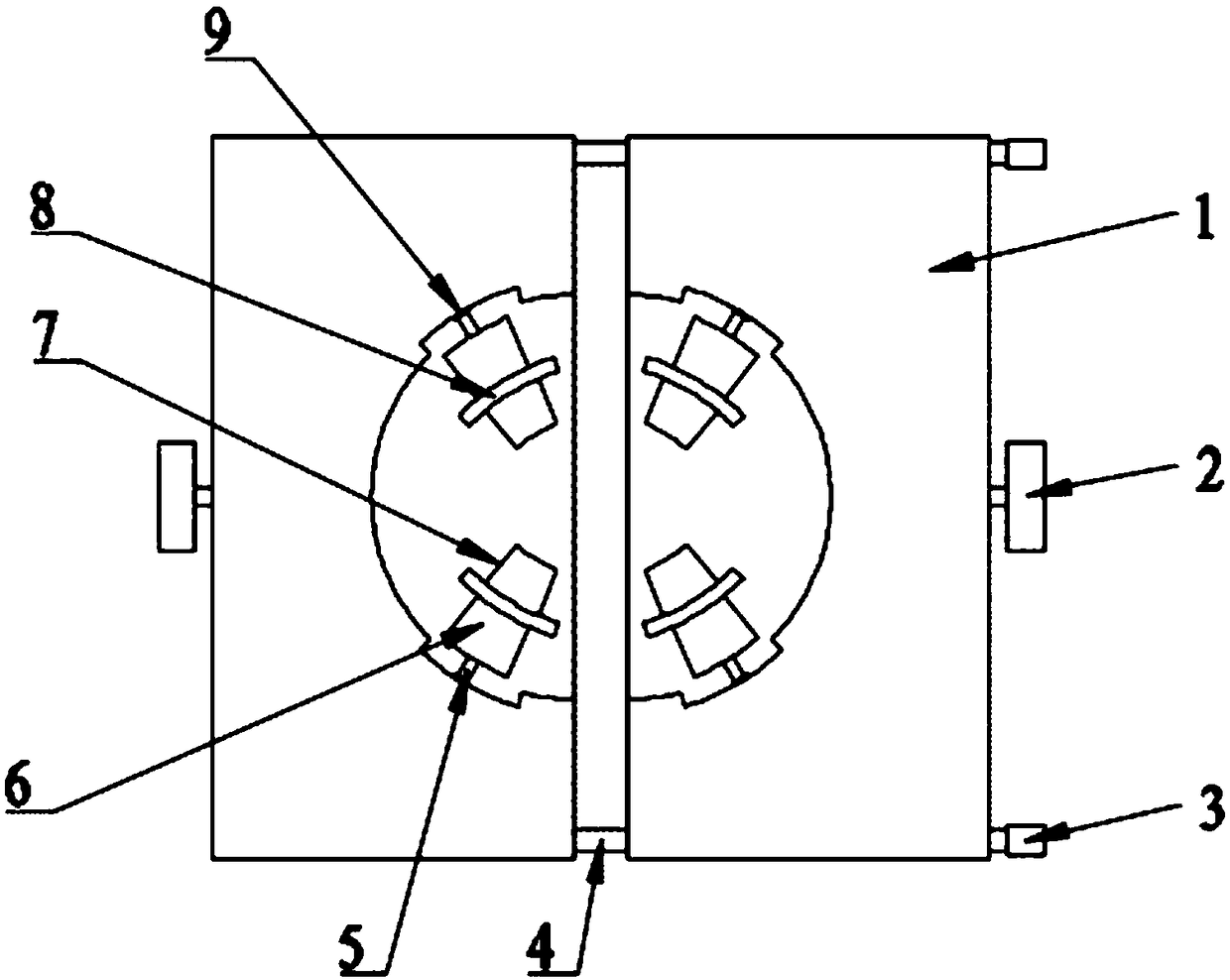
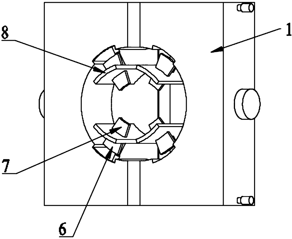
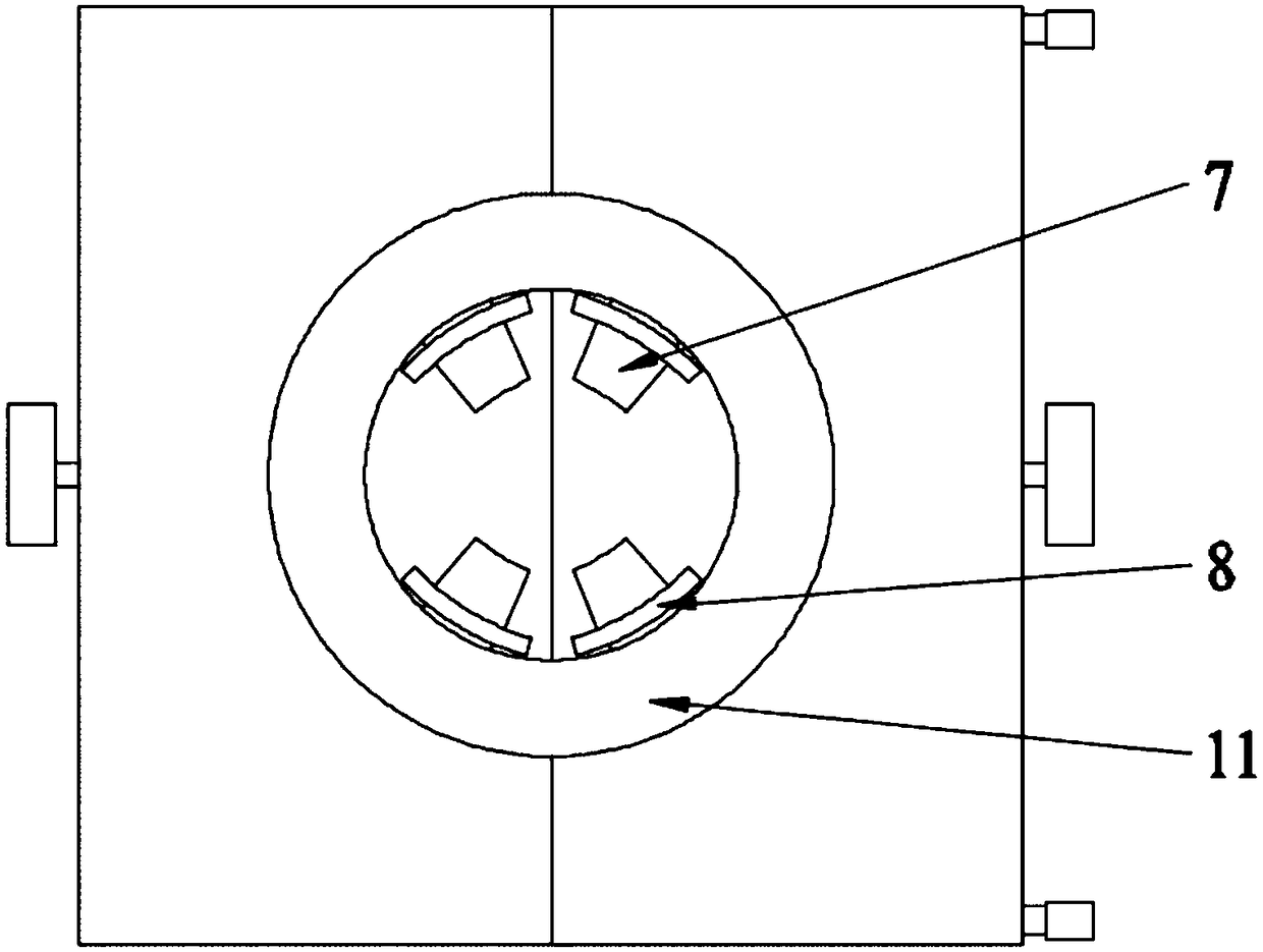
[0030] Such as figure 1 , figure 2 As shown, a tooling fixture for a cylindrical optical element includes a fixed base structure 1 and a clamping device. A through hole is provided in the middle of the fixed base structure 1, and the clamping device includes a plurality of fixedly arranged on the inner wall of the through hole of the fixed base structure 1. Clamping claws 8, a plurality of clamping claws 8 can move in a direction perpendicular to the inner wall of the through hole, thereby forming a form of moving inward or outward along the radial direction of the circular through hole;

[0031] The side wall of the through hole of the fixed bottom plate structure 1 is provided with a groove at the fixed clamping claw 8, and the clamping claw 8 can be retracted into the groove;

[0032] Specifically, in the embodiment of the present application, the middle through ...


PUM


Abstract

The invention discloses a work fixture for a cylindrical optical element. A clamping and fixing structure is formed by utilizing a fixed bottom plate structure and a clamping device; a through hole isformed in the middle of the fixed bottom plate structure; multiple clamping claws are uniformly and fixedly arranged on the inner wall of the through hole of the fixed bottom plate structure and canmove along the direction perpendicular to the inner wall of the through hole, so that a workpiece is clamped; the multiple clamping claws move inwards or outwards along one center so as to fix the optical element, so that the optical element is uniformly stressed, the stability on clamping the optical element is improved, and the clamping claws are prevented from getting loose; and through a locking mechanism, during the detection process of the optical element, the occurrence of the phenomenon that the optical element is inaccurate in centering so as to influence processing or detecting due to the poor stability of the clamping claws and the dead weight of the optical element is avoided.

Description

technical field [0001] The invention relates to a tooling fixture for a cylindrical optical element, which belongs to the field of fixture technology, and is suitable for clamping and installing optical elements without a hole in the center and with a hole in the center through different clamping methods. Background technique [0002] Cylindrical optical elements are widely used in the primary mirror of optical systems. In order to achieve high-precision processing and measurement, it is very important to achieve uniform force clamping and reduce the influence of deformation caused by clamping force. [0003] In the field of optical precision machining, the fixation of optical components includes vacuum chuck, glue, and clamping. Cylindrical optics include center hole and center no hole. For the processing of optical components with holes in the center, the clamping method is generally used for installation, but the components with holes in the center are not easy to clamp ...

Claims


Application Information

Patent Timeline
Patent Type & Authority Applications(China)
IPC IPC(8): B25B11/00
CPCB25B11/00
Inventor 孙林刘剑锋李常胜王鑫垚刘阳鹏方续东韩枫蒋庄德
Owner XI AN JIAOTONG UNIV
Why Eureka
Try Eureka