Clamping device for thin-wall parts

A clamping device and technology for thin-walled parts, applied in the field of clamping devices for clamping thin-walled parts on aerospace testing equipment, to achieve the effects of improving positioning accuracy, uniform clamping, and ensuring no pinch marks

Inactive Publication Date: 2013-01-23
SHANGHAI XINYUE METER FACTORY
View PDF7 Cites 5 Cited by
  • Summary
  • Abstract
  • Description
  • Claims
  • Application Information

AI Technical Summary

Problems solved by technology

[0004] The concept of the present invention is: aiming at the defects of deformation and clamp marks on the thin-walled elastic body produced by the centering clamping mechanism with uniform elastic deformation, the present invention adopts the method of compressing the sealing ring in the axial direction to cause radial deformation to clamp The outer circle of tight thin-walled products is flexible and uniformly deformed, so it can ensure centering without deformation

Method used


Image

  • Clamping device for thin-wall parts

Examples


Embodiment Construction

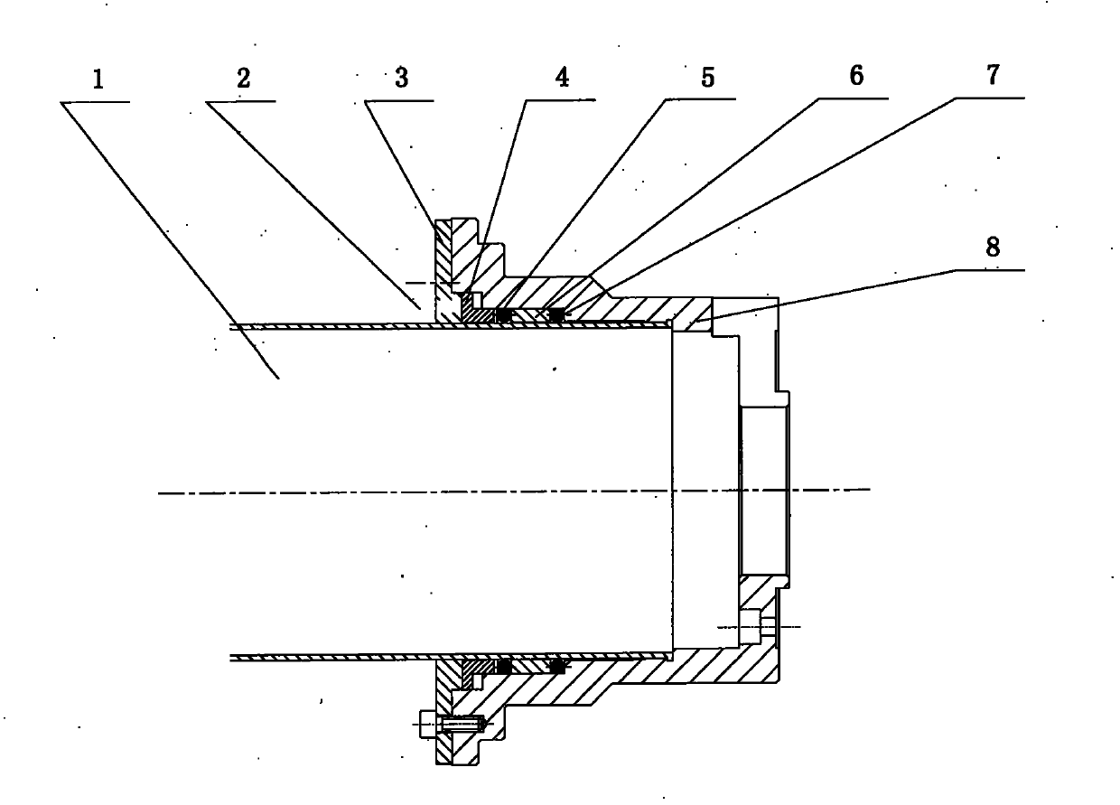
[0013] Such as figure 1 Shown is a schematic structural view of the clamping device for thin-walled parts of the present invention. The structure of the device includes: a flange cover 3, a pressure ring 4, a rubber sealing ring 5, a spacer ring 6, a rubber sealing ring 7, and a chuck cover 8. One end of the outer circle of the chuck sleeve 8 is a flange, and there are two stepped holes in the hole of the chuck sleeve 8. The chuck sleeve 8 is connected with the rotating body on the test equipment through screws; one end of the flange of the chuck sleeve 8 is equipped with a flange The cover 3 and the flange cover 3 are connected with the screw holes of the collet sleeve 8 through six screws; the pressure ring 4, the rubber sealing ring 5, the spacer ring 6, the rubber The sealing ring 7 and the pressure ring 4 are located at one end of the flange cover 3 . The material of the pressure ring 4 is made of 2Cr13 stainless steel rod, and quenched to HRC35-40 to ensure the hardnes...


PUM


Abstract

The invention relates to a clamping device for solving the clamping of thin-wall parts, and provides a clamping device for thin-wall parts. The clamping device for thin-wall-parts structurally comprises a blind flange, sealing rings, a pressing ring, a space ring and chuck sleeve, wherein the blind flange is fixedly connected with the chuck sleeve; the pressing ring, one sealing ring, the space ring and the other sealing ring are arranged in a hole of the chuck sleeve in sequence from the inside out; and the pressing ring is located at one end of the blind flange. By utilizing the flexible deformation of the sealing rings, the outer circles of the thin-wall parts are clamped. Compared with the prior art, the clamping device for thin-wall parts has the advantages and beneficial effects of improving the circle center positioning precision of the thin-wall parts, evenly clamping the thin-wall parts and ensuring that the outer circles of the thin-wall parts are free of clamping mark and deformation. The clamping device is capable of solving the clamping of the outer circles of the thin-wall parts with the wall thickness of 1mm.

Description

technical field [0001] The invention relates to a clamping device, in particular to a clamping device for clamping thin-walled parts on aerospace testing equipment. Background technique [0002] In the field of aerospace, it is necessary to clamp thin-walled products. For example, the wall thickness of the missile body is only 1mm. In order to ensure that the thin-walled parts do not deform during the clamping process, the clamping is required to be firm and the product surface does not produce clamping. mark. The currently commonly used clamping tools are centering clamping mechanisms with uniform elastic deformation, including clamps such as collets, tympanic chucks, and butterfly reeds. However, these clamping devices have the disadvantage that a slightly fierce clamping force will cause deformation of the cartridge case and leave clamping marks. If the clamping force is slightly lighter, it cannot guarantee that the projectile will be hugged. If the fixture is install...

Claims


Application Information

Patent Timeline
Patent Type & Authority Applications(China)
IPC IPC(8): B25B11/00
Inventor 陈岚杨应杰张顺
Owner SHANGHAI XINYUE METER FACTORY
Why Eureka
Try Eureka