Battery charging cradle and mobile electronic device

a charging cradle and battery technology, applied in electric power, electric vehicles, transportation and packaging, etc., can solve the problems of insufficient thinness of the portion of the secondary-side charging adaptor, the inability to charge the battery pack, and the inability to carry ac electric power from the primary coil to the secondary coil, so as to avoid relative misalignment

Inactive Publication Date: 2008-05-15
SANYO ELECTRIC CO LTD
View PDF8 Cites 177 Cited by
  • Summary
  • Abstract
  • Description
  • Claims
  • Application Information

AI Technical Summary

Benefits of technology

[0007]Japanese Patent Laid-Open Publication No. H09-63655 (1997) presents a drawback that when the battery pack is out of alignment on the battery charging cradle, the battery pack cannot be charged. This is because when a relative position between the mobile electronic device and the battery charging cradle is out of alignment, the primary and secondary coils are not electromagnetically coupled to each other, so that the AC electric power cannot be carried from the primary coil to the secondary coil. Such drawback can be remedied, as described in Japanese Utility Model Registration No. 3011829, by providing a positioning protrusion to the battery charging cradle and also providing a positioning recess to the mobile electronic device, for the positioning protrusion to be fitted in the recess. In such structure, the positioning protrusion is guided into the positioning recess, and the relative misalignment can be avoided between the mobile electronic device and the battery charging cradle.
[0011]The above-described mobile electronic device carries the feature that the device can be placed in an accurate position of the battery charging cradle so that the incorporated rechargeable battery is charged positively and stably.
[0013]The above-described mobile electronic device has its incorporated secondary coil, as the coreless planar coil, disposed inside the bottom plate in a parallel relationship to each other, also has a winding diameter in the center of the planar coil to be larger than the inner diameter of the positioning recess, has the hollow portion in the center of the planar coil, and has the positioning recess disposed in the hollow portion. Such unique structure allows the mobile electronic device to dispose the secondary coil in a flush or coplanar relationship with the positioning recess. As such, while being so structured as to incorporate the planar coil and to guide the mobile electronic device to the positioning protrusion of the battery charging cradle in a predetermined position, the bottom surface of the mobile electronic device is made thin enough.
[0018]The above-described battery charging cradle incorporates the position sensor for detecting the position for placement of the mobile electronic device, and the position sensor serves to detect the position for the mobile electronic device to be placed. In particular, when the position for placement of the mobile electronic device is out of alignment with a proper position for placement, an alarm is delivered to notify a misalignment, so that the users are able to set the mobile electronic device to be free from the misalignment alarm, and then is able to stably charge the incorporated rechargeable battery by electromagnetically coupling the primary coil to the secondary coil in a positive manner. Further, according the present invention, when the position for placement of the mobile electronic device is appropriate, a normality indication is given; the users are able to place their mobile electronic device in a proper position while checking such normality indication, and thus the primary coil is electromagnetically coupled to the secondary coil in a positive manner, for stably charging the incorporated rechargeable battery.

Problems solved by technology

H09-63655 (1997) presents a drawback that when the battery pack is out of alignment on the battery charging cradle, the battery pack cannot be charged.
This is because when a relative position between the mobile electronic device and the battery charging cradle is out of alignment, the primary and secondary coils are not electromagnetically coupled to each other, so that the AC electric power cannot be carried from the primary coil to the secondary coil.
The structure shown in Japanese Utility Model Registration No. 3011829, however, presents a drawback that a portion of the secondary-side charging adaptor cannot be made thin enough because the positioning recess is provided to a case bottom and the secondary coil is disposed upon the positioning recess.
Since the mobile electronic device such as a mobile phone is required to be made thinnest possible, an increased thickness caused by the positioning recess presents a drawback that a convenient portability is spoiled.

Method used


Image

  • Battery charging cradle and mobile electronic device
  • Battery charging cradle and mobile electronic device
  • Battery charging cradle and mobile electronic device

Examples


Embodiment Construction

)

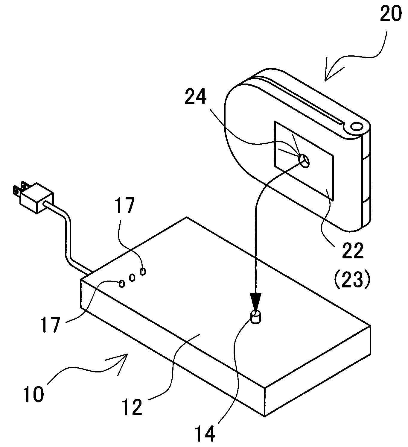
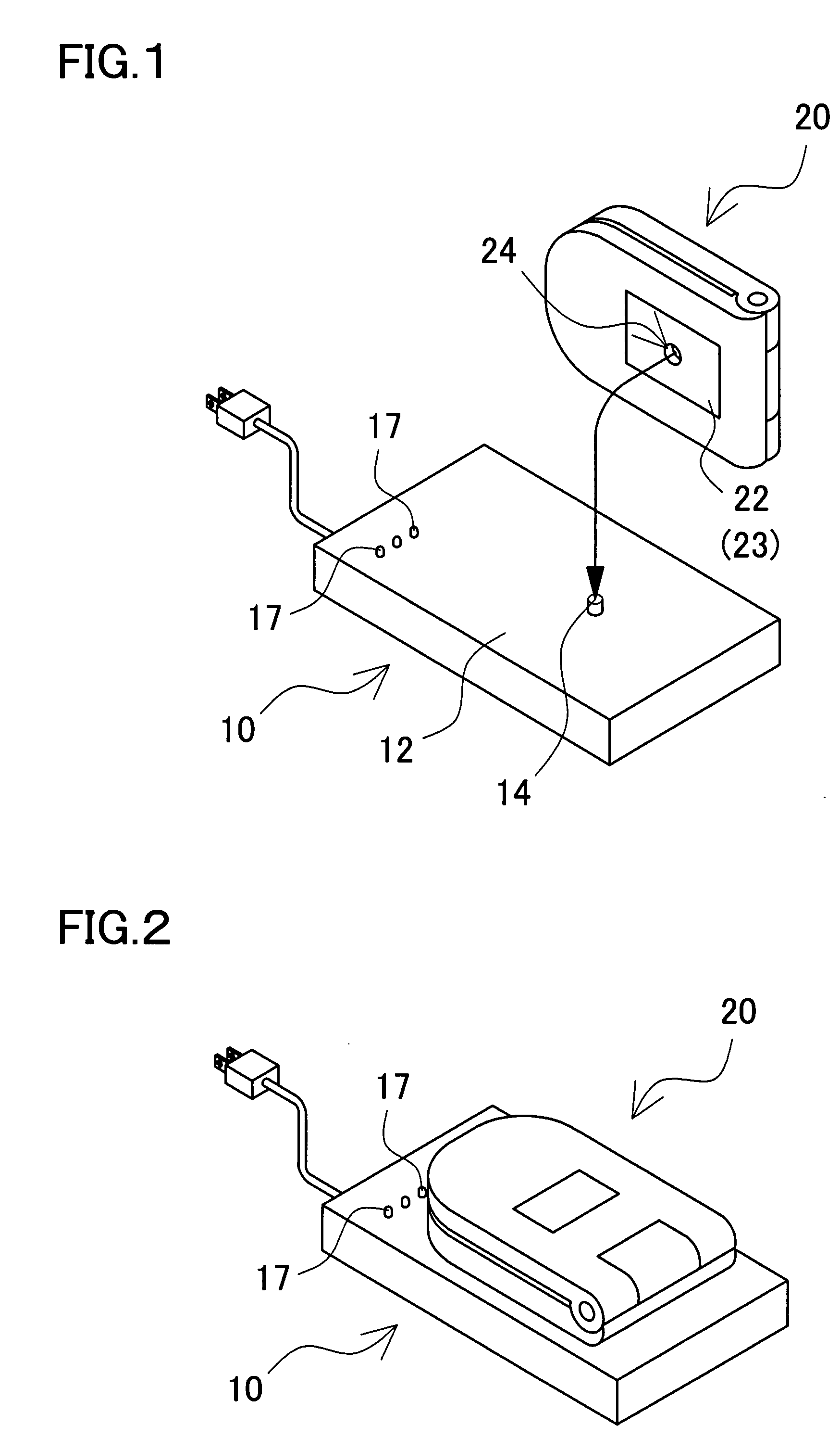
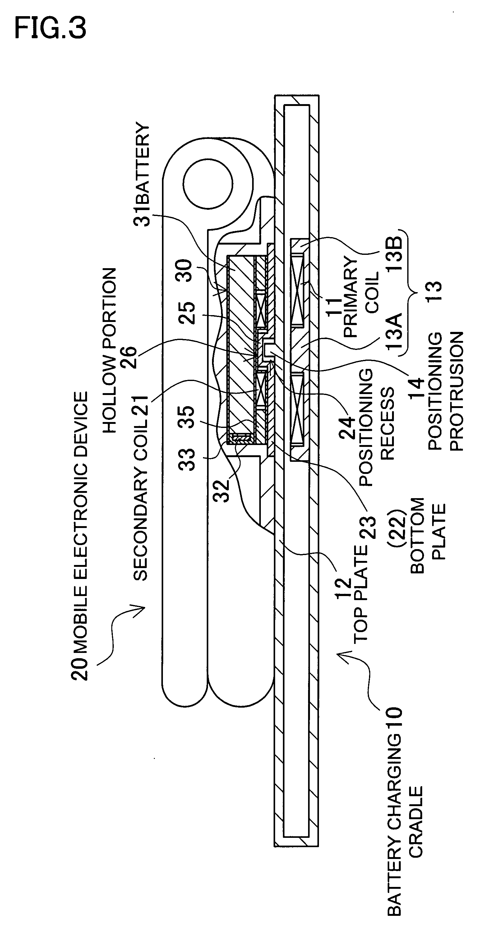
[0041]FIG. 1 through FIG. 6 show a battery charging cradle 10 and a mobile electronic device 20 that is placed on the battery charging cradle 10 to charge an incorporated rechargeable battery 31. The battery charging cradle 10 incorporates a primary coil 11 that is connected to an AC power source 15. The battery charging cradle 10 is provided, on its top surface, with a planar, top plate 12 on which the mobile electronic device 20 is to be detachably placed. In the illustrated battery charging cradle 10, the top plate 12 is planar in its entirety and is disposed horizontally. The battery charging cradle 10 allows a variety of mobile electronic devices 20 in different sizes and shapes to be placed on the cradle so that the incorporated rechargeable battery can be charged. The battery charging cradle, however, may also be provided with a peripheral wall on around the cradle, so that the mobile electronic device may be placed inside the peripheral wall so as to charge the incorporated...


PUM


Abstract

A battery charging cradle and mobile electronic device include a battery charging cradle incorporating a primary coil which induces an AC magnetic flux to a specific portion of a planar, top plate of the cradle, and a rechargeable battery incorporated inside a bottom plate and charged by electric power which is induced to a secondary coil being electromagnetically coupled to the primary coil. The battery charging cradle has a positioning portion, so that the mobile electronic device is placed in a predetermined position by means of the positioning portion, the primary coil is electromagnetically coupled to the secondary coil, and thus the rechargeable battery incorporated in the mobile electronic device is charged.

Description

BACKGROUND OF THE INVENTION[0001]1. Field of the Invention[0002]The present invention relates to a battery charging cradle and mobile electronic device, where the mobile electronic device is placed on the battery charging cradle so that electric power is carried from the battery charging cradle to the mobile electronic device by an electromagnetic induction effect to charge a rechargeable battery incorporated in the mobile electronic device.[0003]2. Description of the Related Art[0004]There have been developed a battery charging cradle and mobile electronic device, where electric power is carried from a primary coil to a secondary coil by the effect of an electromagnetic induction to charge a rechargeable battery. Refer to Japanese Patent Laid-Open Publication No. H09-63655 (1997) and Japanese Utility Model Registration No. 3011829.[0005]Described in Japanese Patent Laid-Open Publication No. H09-63655 (1997) is a structure that the primary coil excited by an AC power source is incor...

Claims


Application Information

Patent Timeline
Patent Type & Authority Applications(United States)
IPC IPC(8): H02J7/00
CPCH02J7/025H02J7/0044H02J50/90H02J50/12H02J50/70
Inventor TOYA, SHOICHI
Owner SANYO ELECTRIC CO LTD
Why Eureka
Try Eureka