
Image processing apparatus, imaging apparatus, and computer readable medium

a technology of image processing apparatus and imaging apparatus, which is applied in the field of image processing apparatus, imaging apparatus, and computer readable medium, can solve the problems of adding random noise to a signal at an almost saturated level, and the inability to obtain dither effect, etc., and achieve excellent highlight expression

Inactive Publication Date: 2008-05-15
NIKON CORP
View PDF9 Cites 4 Cited by
  • Summary
  • Abstract
  • Description
  • Claims
  • Application Information

AI Technical Summary

Benefits of technology

[0009]Accordingly, an object of the present invention is to provide an image processing apparatus and a computer readable medium in which a dither effect around a highlight area can be obtained easily and certainly, and to provide an imaging apparatus which is excellent in highlight expression.
[0021]Accordingly, the present invention realizes an image processing apparatus and a computer readable medium in which a dither effect around a highlight area can be obtained easily and certainly. Also, the present invention realizes an imaging apparatus which is excellent in highlight expression.

Problems solved by technology

This technique intentionally adds random noise to a signal at an almost saturated level.
However, if this signal processing technique is applied to an electronic still camera without any modification, it is found that the dither effect can not always be obtained depending on an application method and a use condition thereof.

Method used


Image

  • Image processing apparatus, imaging apparatus, and computer readable medium
  • Image processing apparatus, imaging apparatus, and computer readable medium
  • Image processing apparatus, imaging apparatus, and computer readable medium

Examples


first embodiment

[0031]Hereinbelow, a first embodiment according to the present invention will be described.

[0032]The present embodiment is an embodiment for an electronic still camera system.

[0033]First, a configuration of a present system will be described.

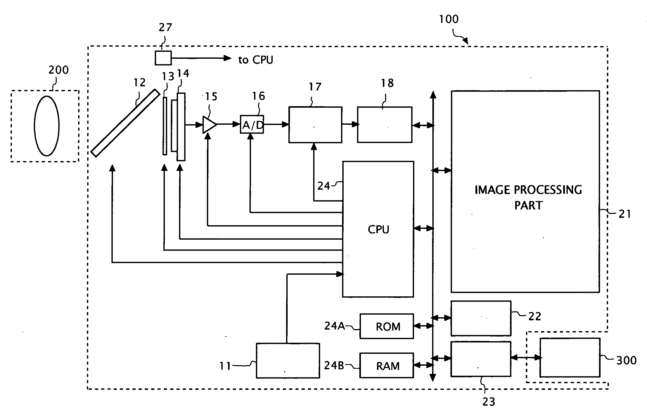
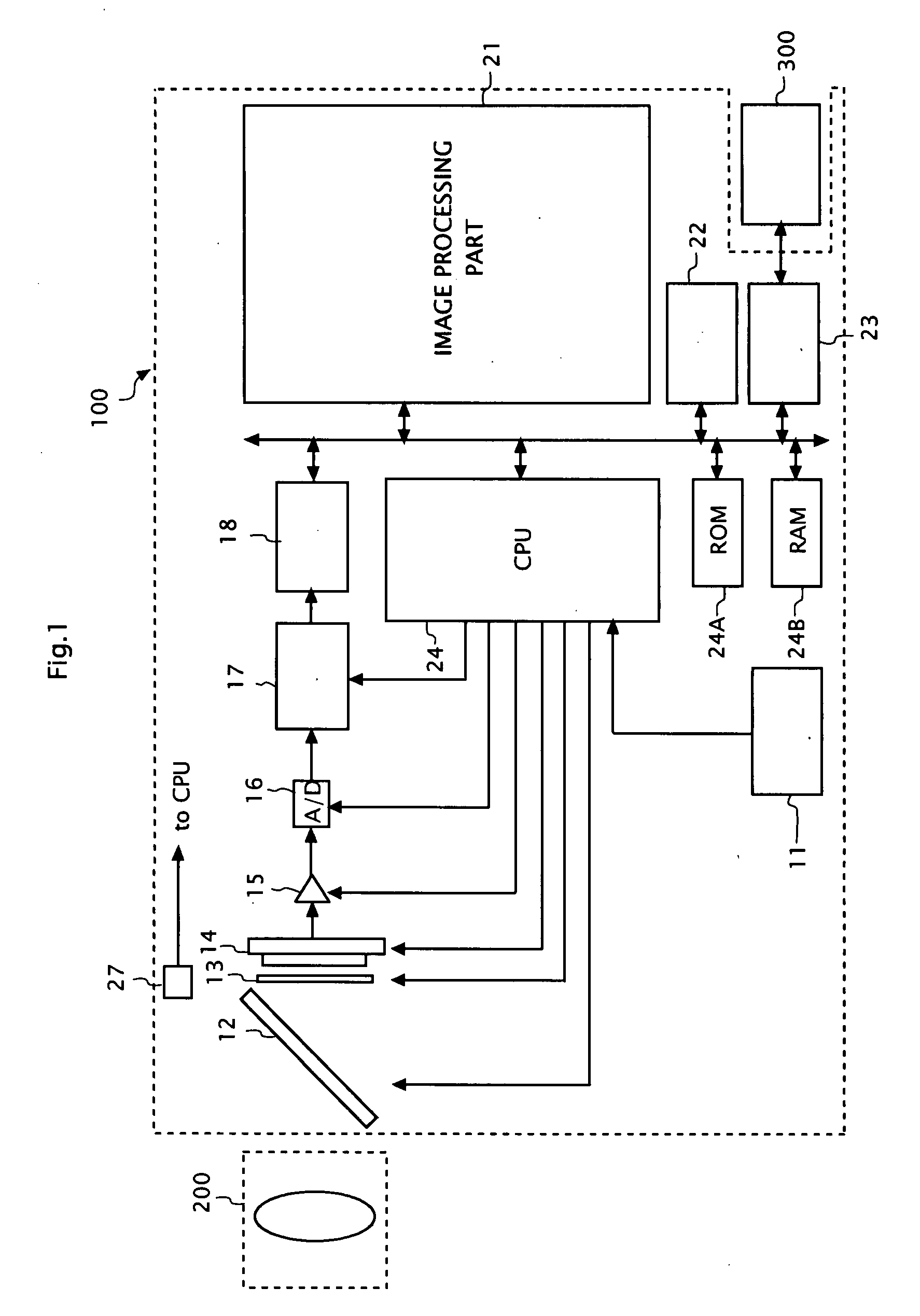
[0034]FIG. 1 is a functional block diagram of the present system. As shown in FIG. 1, the present system includes an electronic still camera body 100 and a shooting lens 200 attached to the electronic still camera body 100.

[0035]The electronic still camera body 100 is attached with a portable storage medium 300 such as a card memory and includes an operating button 11, a quick-return mirror 12, a shutter 13, a color imaging sensor (CCD, CMOS, etc.) 14, an amplifier 15, an A / D converter 16, a signal processing circuit 17, a frame memory 18, an image processing part 21, a compressionnal / decompressional processing part 22, a storaging part 23, a CPU 24, a ROM 24A, a RAM 24B, a photometric sensor 27, etc. The ROM 24A preliminarily stores an operatin...

second embodiment

[0079]Hereinbelow, a second embodiment according to the present invention will be described. The present embodiment is also an embodiment for an electronic camera system. Here, only differences from the first embodiment will be described.

[0080]A user of a present system can specify a shooting sensitivity (ISO sensitivity) such as “1,600”, “800”, “400”, “200”, or “100” to the present system in a setting mode. A CPU 24 in the present system recognizes an ISO sensitivity specified by the user, and set a gain of an amplifier 15 accordingly (a higher gain is set for a larger specified value).

[0081]Also, the CPU 24 in the present system carries out generation and setting of a tone-converting table according to specifications for the ISO sensitivity and the tone correction degree in the setting mode. That is, in the present system, the generation and setting of the tone-converting table is carried out in a setting mode, not in a shooting mode.

[0082]FIG. 8 is an operational flow chart of th...


PUM


Abstract

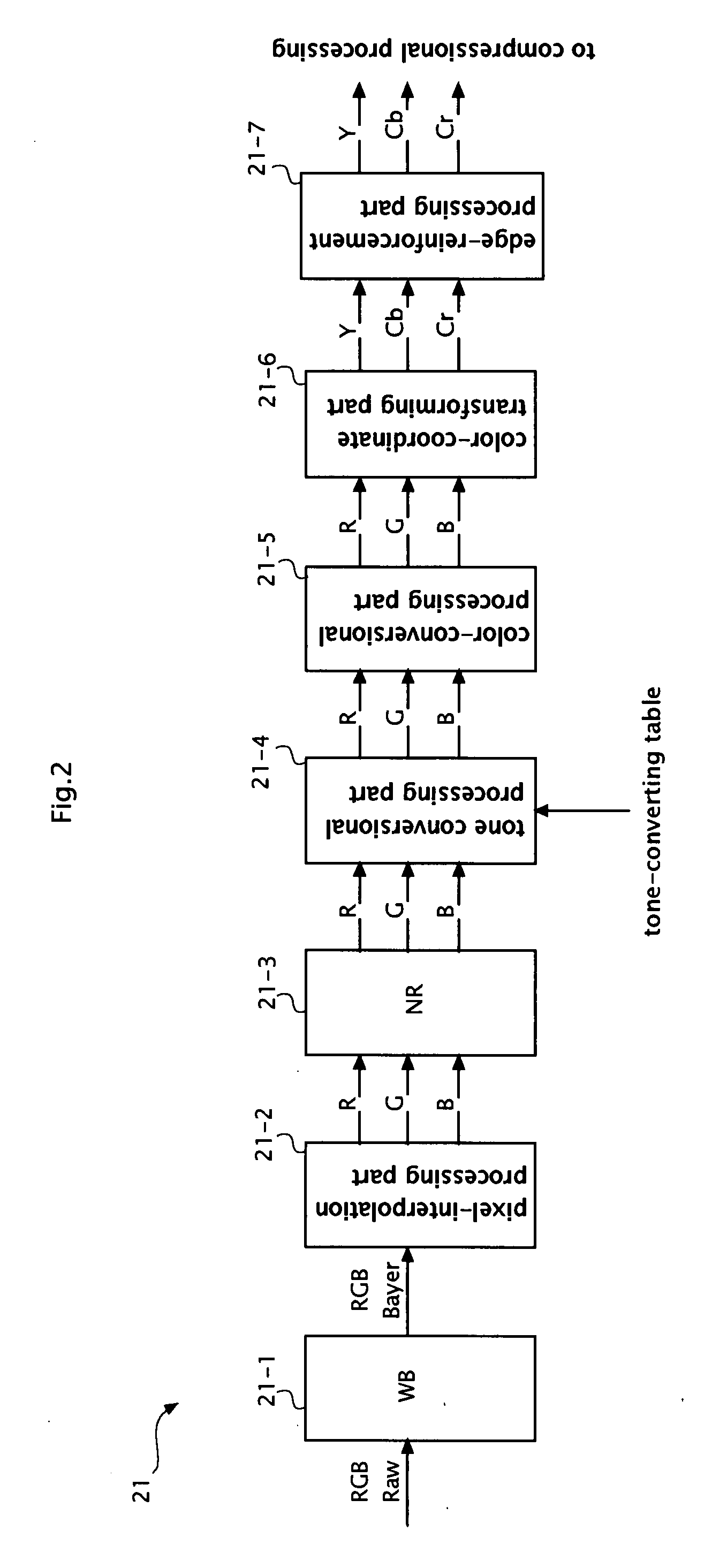
An image processing apparatus, a computer readable medium and the like in which a dither effect in a neighborhood of a highlight area can be obtained easily and certainly. For this purpose, an image processing apparatus includes an inputting unit which inputs a pixel signal group representing a field image, an averaging unit (21-2 and 21-3) which performs a processing having an averaging effect among the pixel signal group input by the inputting unit, and an irregularizing unit (21-4) which irregularizes mutually continuous signal-values at least near a saturated level among the pixel signal group after having been processed by the averaging unit, into discontinuous signal-values.

Description

CROSS-REFERENCE TO RELATED APPLICATION[0001]This application is based upon and claims the benefit of priority from Japanese Patent Application No. 2006-300684, filed on Nov. 6, 2006, the entire contents of which are incorporated herein by reference.BACKGROUND[0002]1. Field[0003]The present invention relates to an image processing apparatus mounted in an electronic still camera and the like, an imaging apparatus such as an electronic still camera, and a computer readable medium.[0004]2. Description of the Related Art[0005]When there is an outstandingly bright object in a field to be photographed with a camera, there arises a highlight area (saturated white area) at a part of a photographed image. This highlight area has a completely flat tone differently from other area and a distinguished outline thereof provides a viewer with an unnatural impression.[0006]The patent reference 1 discloses a signal processing technique to make the outline unnoticeable. This technique intentionally ad...

Claims


Application Information

Patent Timeline
IPC IPC(8): H04N5/228G06T5/00H04N1/407H04N5/20H04N5/232H04N101/00
CPCH04N1/407H04N5/213H04N1/409
Inventor HATTORI, YUKONISHIZAWA, TSUTOMU
Owner NIKON CORP
Learn More