Non-occluding dilation device

a dilation device and non-occluding technology, applied in the field of medical devices, can solve the problems of limited time for balloon dilators to be dilated, occlusion of blood flow, harming patients,

Inactive Publication Date: 2008-05-15
MERIT MEDICAL IRELAND LTD
View PDF69 Cites 68 Cited by
  • Summary
  • Abstract
  • Description
  • Claims
  • Application Information

AI Technical Summary

Benefits of technology

[0024] The present invention provides a device for dilating either a vessel or a structure positioned within the vessel. The device may be used in any medical application in which dilation of a vessel and / or dilation of a structure positioned within a vessel (e.g., a stent or stent graft, such as a thoracic or abdominal aortic stent graft) is desired. The device is designed so that when it is expanded it does not occlude or substantially hinder the flow of fluid through the vessel or through side vessels are connected to the vessel. The device includes a plurality of wires and has a first position in which the device is not dilated and can be moved into or retrieved from a vessel, and a second position in which the device is dilated and dilates the vessel and / or a structure within the vessel. When dilated, fluid passes through openings between the wires rather than being occluded or substantially hindered.

Problems solved by technology

Such an occlusion of blood flow could, if continued for too long, harm the patient, since portions of the body downstream of the balloon dilator will not receive blood while the flow is occluded or substantially hindered.
Thus, the length of time balloon dilators may be dilated is limited and this can hinder proper completion of the dilation procedure.
A similar problem with balloon dilators arises when a dilation procedure is being performed in a portion of the circulatory system where there is a branch in the blood vessels, such as where the iliac or renal arteries are side vessels that branch from the aorta.
Another problem with balloon-like dilators is called the “windsock effect.” Because blood flow is substantially or entirely occluded when balloon dilators are dilated, the blood pressure upstream of the balloon dilator can be significant and may cause the balloon dilator, and any structure (such as a stent or stent graft) positioned in the blood vessel and that is being dilated by the balloon dilator, to move out of the desired position, effectively pushed down stream (i.e., in the antegrade direction) by the upstream blood pressure.
Because of this problem accurate placement of such structures can be difficult utilizing balloon dilators.

Method used


Image

  • Non-occluding dilation device
  • Non-occluding dilation device
  • Non-occluding dilation device

Examples


Embodiment Construction

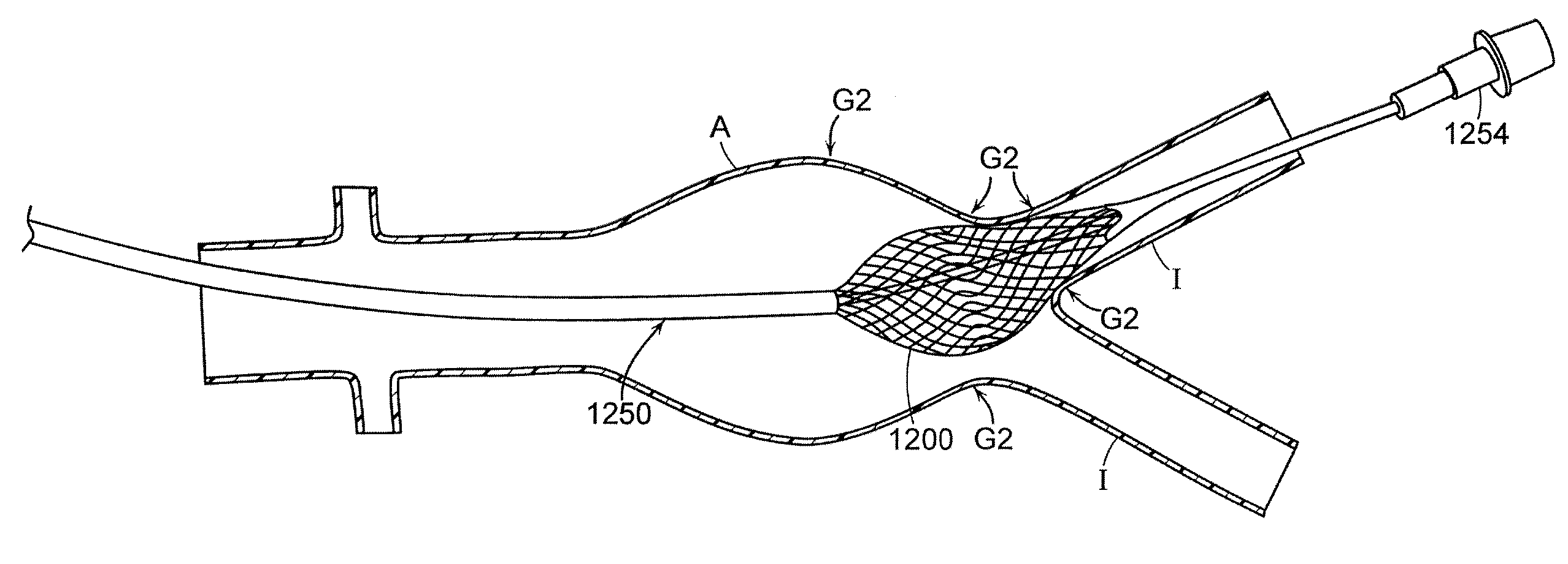
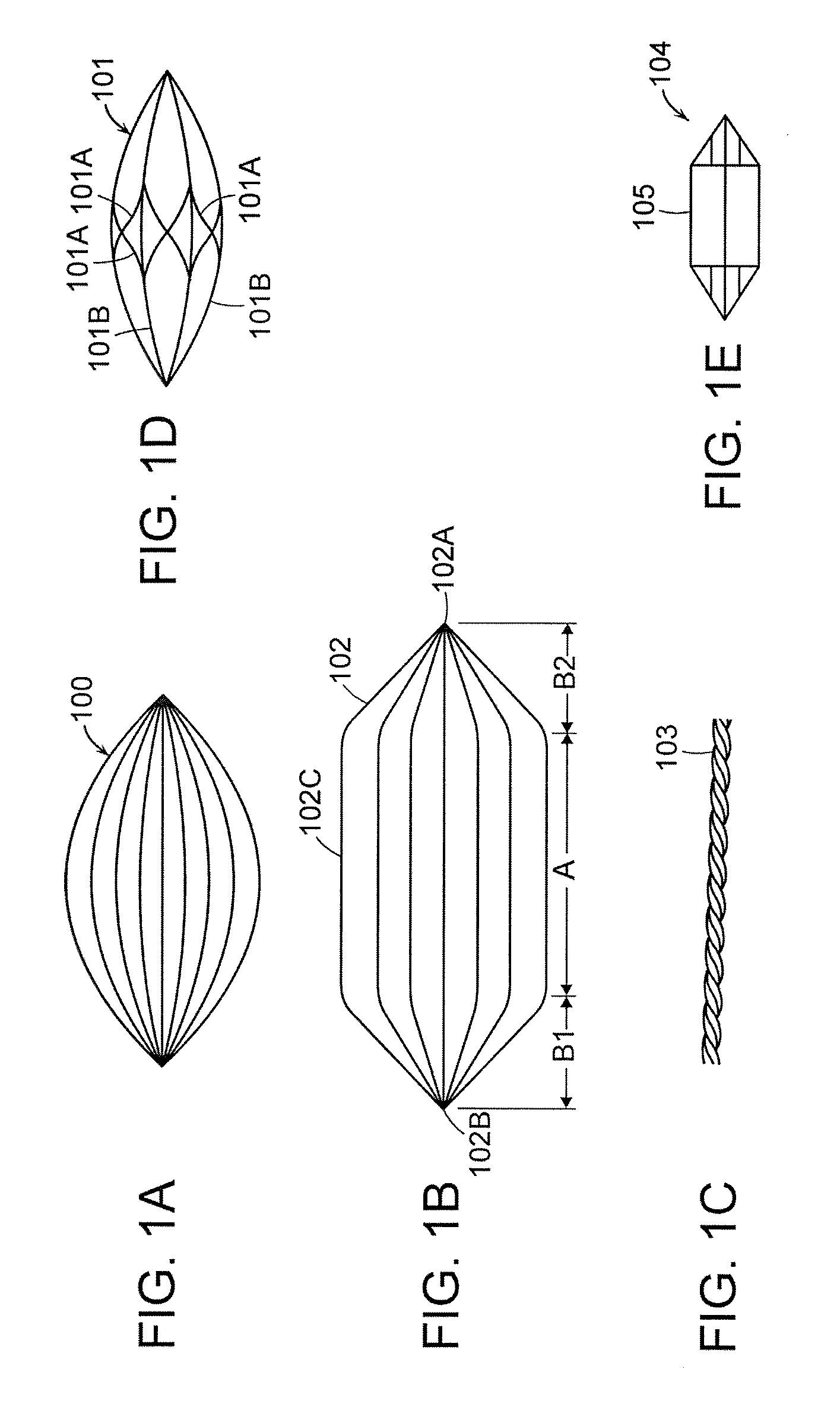
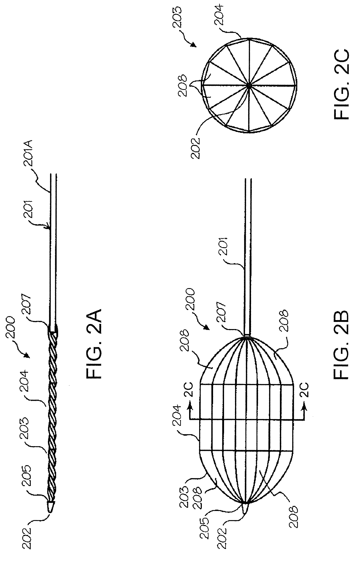
[0057] A device according to the invention is for dilating a vessel and / or a structure (such as an endograft, stent or stent graft) positioned in the vessel, or alternatively may be used to simultaneously dilate two vessels or dilate a structure positioned in two vessels. The device comprises a plurality of wires and has a first position wherein it is collapsed. In this first position the device has a sufficiently small enough diameter to be positioned in a vessel where it is to be used. The device also has a second position wherein it is dilated in order to dilate a vessel and / or a structure within the vessel. When dilated the wires of the device are spaced apart to allow for the passage of fluid through the device. Thus, the device is designed so that it does not occlude or substantially hinder the flow of fluid through the vessel.

[0058] A device according to the invention may have a collapsed diameter sufficient to fit into any suitable catheter. A device according to the invent...


PUM


Abstract

An assembly including a device for dilating a vessel or a structure (such as a stent or stent graft) within a vessel wherein the device comprises a plurality of wires that are spaced apart when the device is dilated so as to allow fluid to flow through the device. Thus, when in use the device does not occlude or substantially hinder the flow of blood through a vessel or into side vessels. The device may also be flexible enough to be easily maneuvered through tight bends in a vessel and/or be able to conform to varying diameters within a single vessel or within multiple vessels.

Description

CROSS REFERENCE TO RELATED APPLICATIONS [0001] This application is a continuation-in-part of and claims priority to (1) U.S. Utility application Ser. No. 11 / 820,726, filed Jun. 19, 2007 (FIGS. 8 through 26 of which are incorporated herein by reference), which is a continuation-in-part of U.S. Utility application Ser. No. 11 / 478,340, filed Jun. 28, 2006, which claims the benefit of Provisional Application No. 60 / 595,378, filed Jun. 28, 2005, and (2) to U.S. Utility application Ser. No. 11 / 478,340 filed Jun. 28, 2006.FIELD OF THE INVENTION [0002] The present invention relates generally to medical devices, and more particularly to a medical device for the dilation of blood vessels and / or the dilation of structures positioned within blood vessels. BACKGROUND OF THE INVENTION [0003] Conventional systems for dilating blood vessels and / or structures (e.g., stents or stent grafts) positioned in a blood vessel utilize balloon-like structures (“balloon dilators”). Such structures are typicall...

Claims


Application Information

Patent Timeline
Patent Type & Authority Applications(United States)
IPC IPC(8): A61F2/90A61F2/84
CPCA61F2/88A61F2/95A61F2/958A61F2230/005A61M29/02A61F2230/0008A61F2250/0059
Inventor RAMAIAH, VENKATESHMCNUTT, ROBERT
Owner MERIT MEDICAL IRELAND LTD
Why Eureka
Try Eureka