Floor Profile Arrangement Comprising a Joint

a technology of floor profile and joint, which is applied in the direction of resiliently mounted floors, walls, flooring, etc., can solve the problem of relatively limited height differences between adjacent floor coverings, and achieve the effect of greater height differences

Inactive Publication Date: 2008-05-22
HERM FRIEDR KUENNE GMBH & CO
View PDF7 Cites 3 Cited by
  • Summary
  • Abstract
  • Description
  • Claims
  • Application Information

AI Technical Summary

Benefits of technology

[0004]The invention is based upon the objective of improving a joint bridging arrangement of the type specified in the

Problems solved by technology

The height differences which can be bridged between the a

Method used


Image

  • Floor Profile Arrangement Comprising a Joint
  • Floor Profile Arrangement Comprising a Joint
  • Floor Profile Arrangement Comprising a Joint

Examples


Embodiment Construction

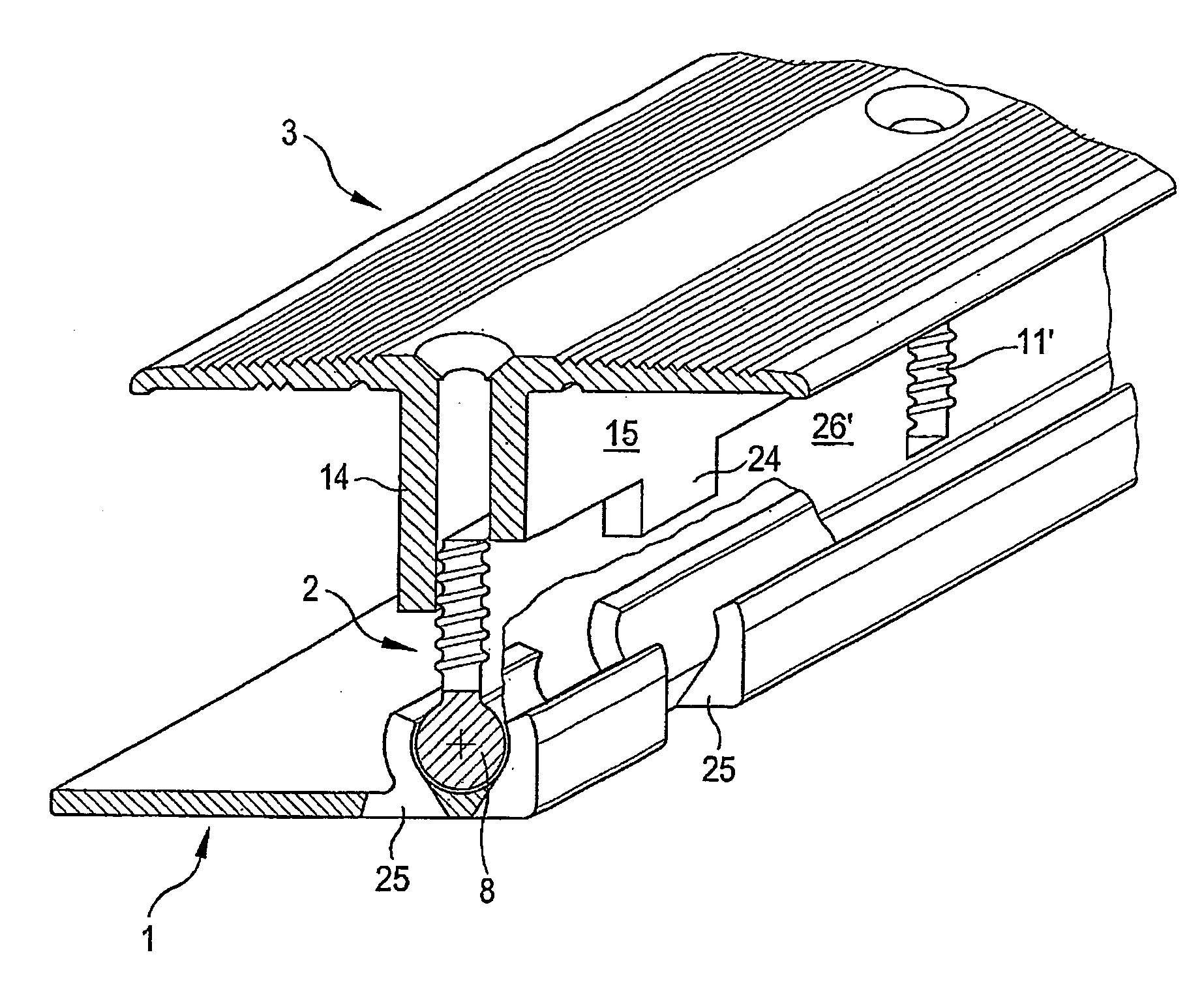
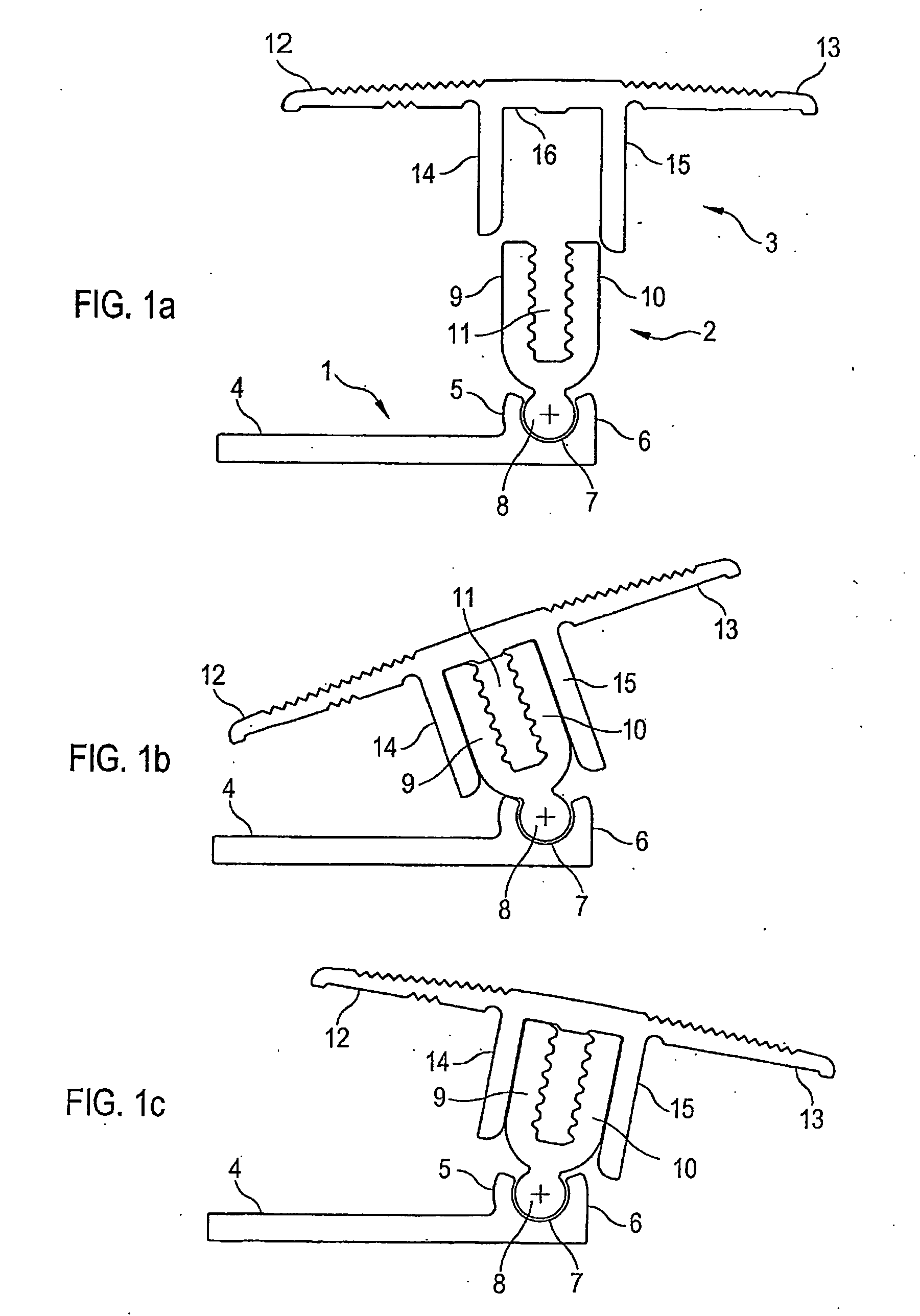
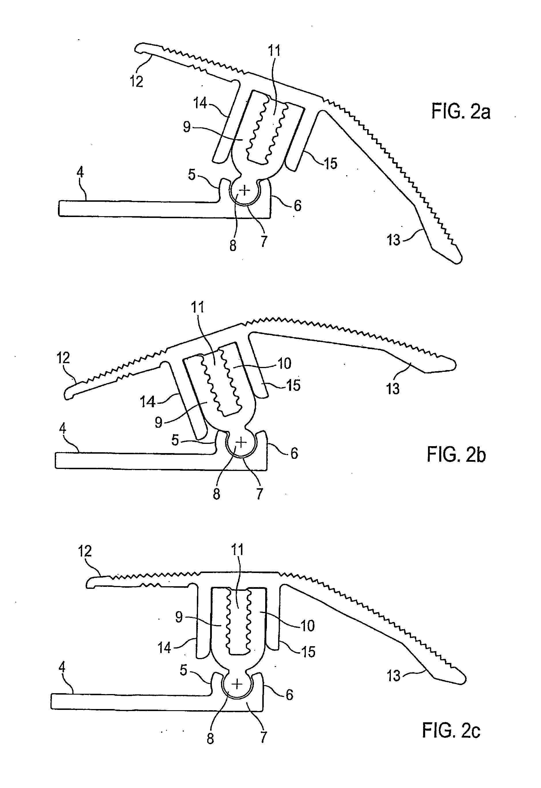
[0034]The joint bridging arrangement shown in different fitted states in FIGS. 1a to 1c is formed in three parts and consists essentially of a base profile 1, a web arrangement 2 and a covering profile 3.

[0035]The base profile 1 is essentially designed in an L-shape and has a horizontal side piece 4 which is screwed onto the floor by means of a screw (not shown). Furthermore, the base profile 1 has two side pieces 5, 6 extending upwards into the joint and between which a partially hollow-cylindrical articular cavity 7 is formed into which a partially cylindrical articulation element 8 formed on the lower side of the web arrangement 2 engages so that the web arrangement 2 can pivot relative to the base profile 1.

[0036]Furthermore, on its upper side the web arrangement 2 has two upwardly extending parallel side pieces 9, 10, between which a threaded channel 11 for accommodating a screw (not shown) is formed, and which is realised by means of a hole (not shown) in the covering profile ...


PUM


Abstract

A floor profile arrangement is provided, in particular for bridging a joint between adjacent floor coverings, with a base profile, a covering profile with at least one sideways projecting covering wing, and a web arrangement as a connection between the base profile and the covering profile, and with an articulation arrangement, the articulation arrangement consisting of an articular cavity disposed on the base profile or the covering profile and an articulation element formed on the lower or on the upper edge of the pivoting web arrangement.

Description

TECHNICAL FIELD OF THE INVENTION[0001]The invention relates to a floor profile arrangement, in particular for bridging a joint between two adjacent floor coverings, according to claims 1 and 2.BACKGROUND OF THE INVENTION[0002]A joint bridging arrangement for a floor is known from DE 199 51 516 A1 which, for example, makes it possible to bridge a joint in a parquet floor with different heights on either side of the joint. This known joint bridging arrangement consists of a substantially L-shaped base profile, which is screwed onto the floor, and two side pieces extending upwards into the joint. A covering profile with two covering wings projecting sideways is disposed over the joint to be bridged, the covering wings lying over the adjacent floor coverings when in fitted state and being elastically adaptable to different heights of the floor coverings. With the known joint bridging arrangement a web arrangement is provided between the covering profile and the base profile, said web ar...

Claims


Application Information

Patent Timeline
IPC IPC(8): E04F19/06
CPCE04F19/062E04F19/067E04F19/066E04F19/063E04F15/02022E04F15/02044E04F19/061E04F19/065E04F2015/02105
Inventor SONDERMANN, FRANK
Owner HERM FRIEDR KUENNE GMBH & CO
Why Eureka
Try Eureka