
Eureka
For R&D, Eureka makes reading and utilizing patents & technical documents easy.
Eureka AIR
Designed for self-driven R&D workflows. Generate viable solutions, solve complex R&D challenges, empower your innovation with AI.

Eureka Materials
Designed for material experts only. Revolutionize your material R&D, from search, analyze, to developing new materials.

TechResearch
Generate reliable direction feasibility study reports for your R&D in just a few steps.

TechSeek
Discover and master advanced knowledge NOW. Basics, ideas, possibilities, all at once.

TechMind
As an expert in R&D Theories, TechMind can generates customized viable solutions instantly.

TechRisk
Analyze your overall solution with one click, know your potential R&D risks in advance.

TechMonitor
Get weekly tech updates, stay abreast of the latest tech innovations and key insights.
Cutting apparatus for cutting tiles
- Summary
- Abstract
- Description
- Claims
- Application Information
AI Technical Summary
Benefits of technology
Problems solved by technology
Method used
Image

Examples
Embodiment Construction
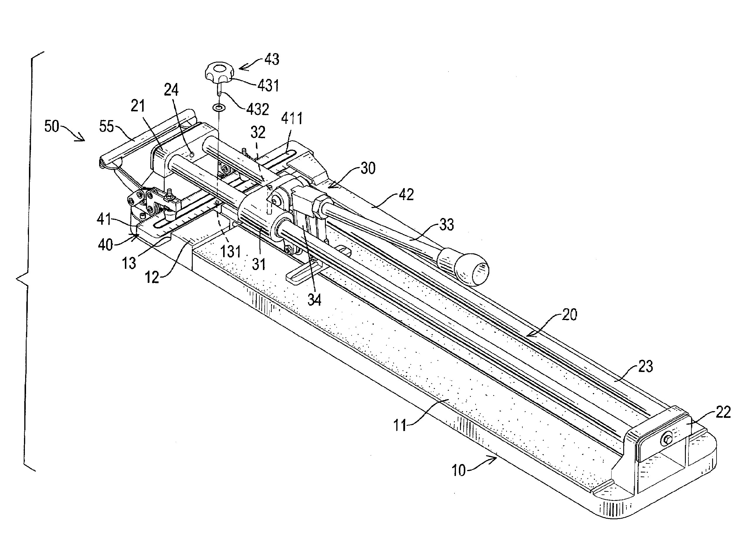
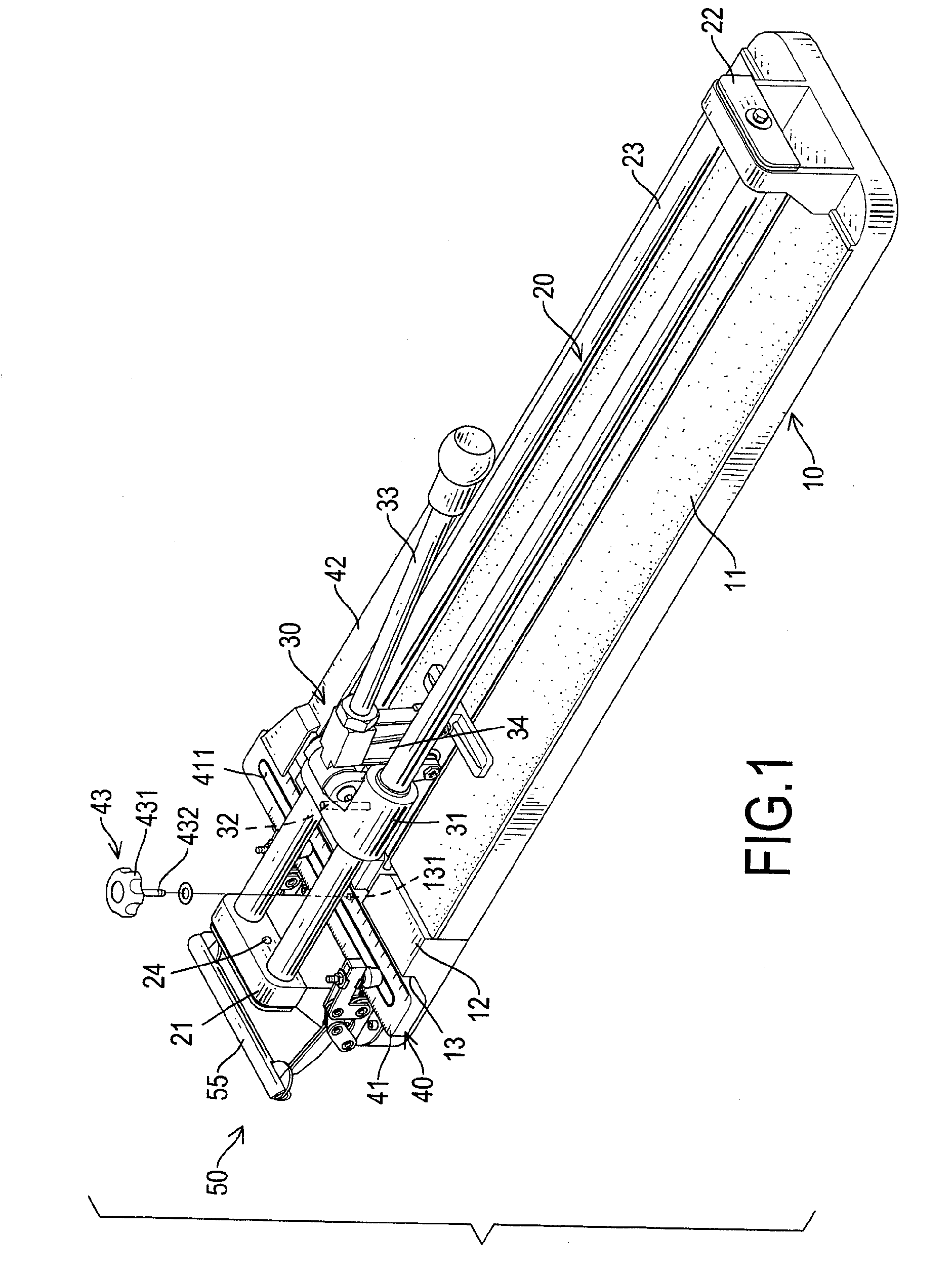
[0023]With reference to FIGS. 1 to 3, a cutting apparatus in accordance with the present invention for cutting tiles comprises a base (10), a rail device (20), a cutting device (30), a positioning ruler (40) and a clamping apparatus (50).
[0024]The base (10) may be rectangular and has a top (11), a proximal end, a distal end (12) and an elongated slot (13). The elongated slot (13) is defined near the distal end (12) of the base (10) and has a bottom and a setscrew hole (131). The setscrew hole (131) is formed in the bottom of the elongated slot (13).
[0025]The rail device (20) is connected to the base (10) over the top (11) and has a first support (21), a second support (22) and two rail-posts (23). The first support (21) is formed on the distal end (12) of the base (10) near the elongated slot (13) and has a sidewall and a first laser device (24). The sidewall of the first support (21) is defined near the elongated slot (13). The first laser device (24) is mounted slantwise in the fi...
PUM
 Abstract
Description
Claims
Application Information
 - R&D Engineer
- R&D Manager
- IP Professional
- Industry Leading Data Capabilities
- Powerful AI technology
- Patent DNA Extraction
Browse by: Latest US Patents, China's latest patents, Technical Efficacy Thesaurus, Application Domain, Technology Topic, Popular Technical Reports.
© 2024 PatSnap. All rights reserved.Legal|Privacy policy|Modern Slavery Act Transparency Statement|Sitemap|About US| Contact US: help@patsnap.com