Knee-protecting airbag device

Inactive Publication Date: 2008-05-22
TOYODA GOSEI CO LTD
View PDF5 Cites 47 Cited by
  • Summary
  • Abstract
  • Description
  • Claims
  • Application Information

AI Technical Summary

Benefits of technology

[0046]With such a configuration, the lateral width dimension of the folded airbag and the inflator can be reduced. Thus, the airbag device acco

Problems solved by technology

But, because of the facts that the column cover itself protrudes from the instrument panels, and that an airbag protrudes from the bottom surface side of a protruding part of the column cover, the airbag is liable to complete inflation thereof so as to be detached backwardly from and float with respect to the rear surface of each of the instrument panels.
Thus, even when the knee being forwardly moving abuts against a part of the airbag, which is spac

Method used


Image

  • Knee-protecting airbag device
  • Knee-protecting airbag device
  • Knee-protecting airbag device

Examples


first embodiment

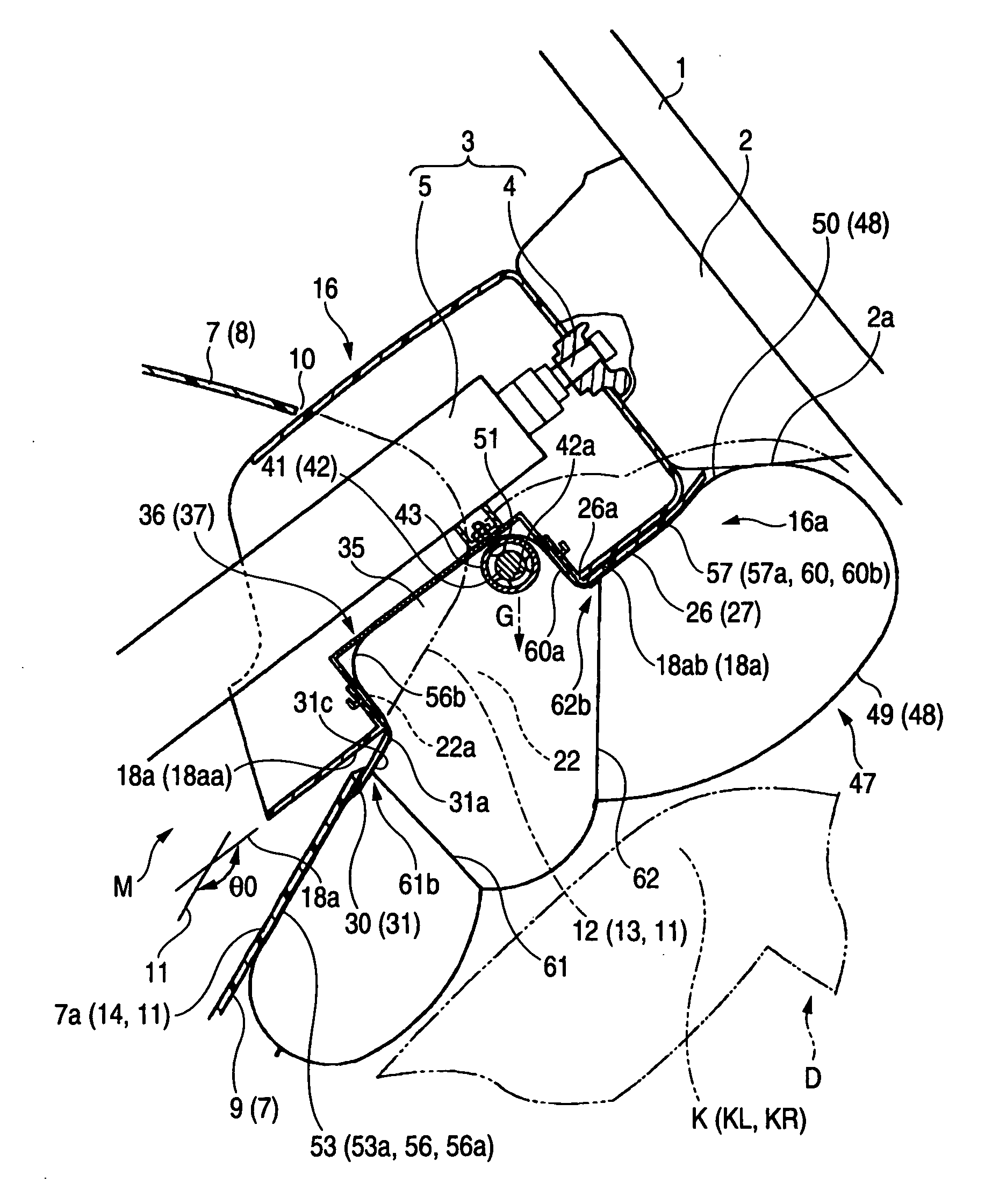
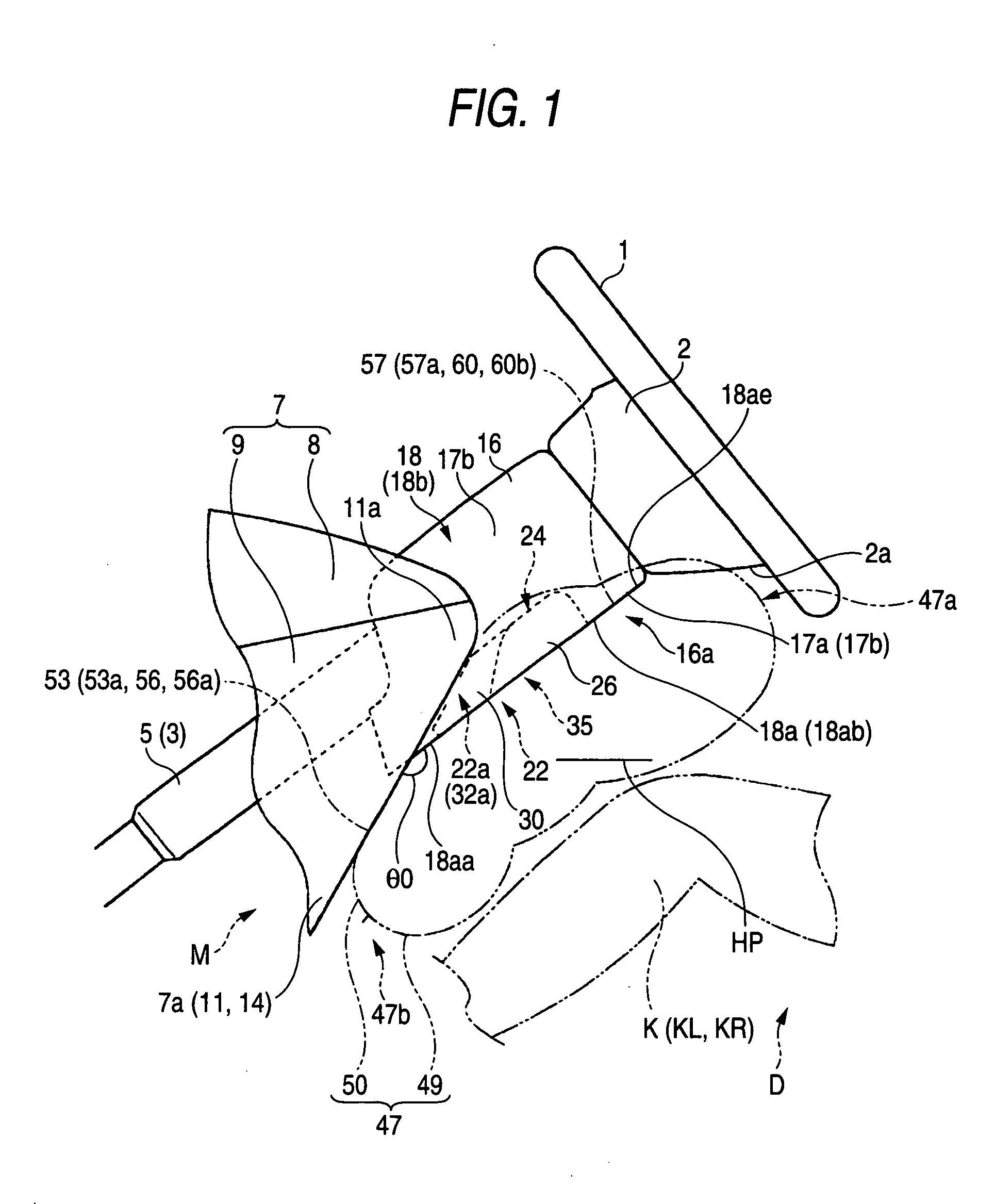
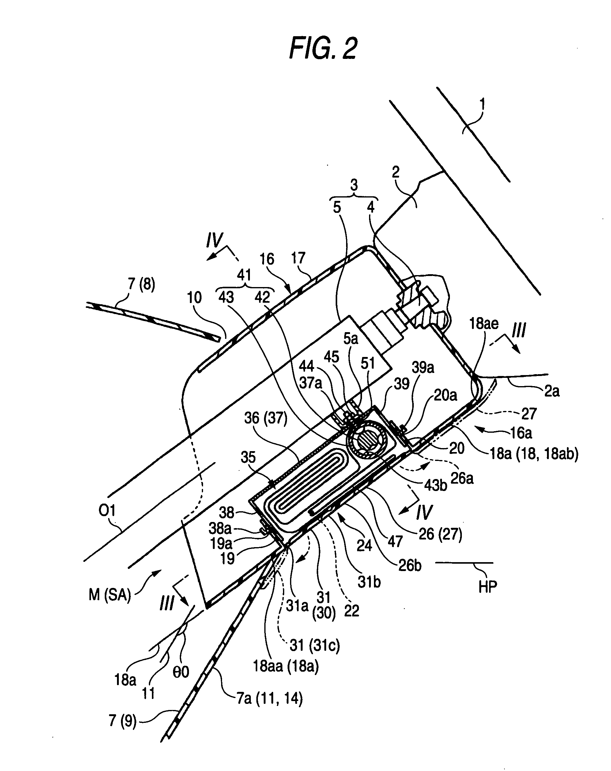
[0086]Additionally, in the first embodiment, as illustrated in FIGS. 3, 5, and 11, an auxiliary door portion 30 to be force-opened toward the airbag 47 so as to increase the area of the projection opening 22 of the airbag 47 is provided at the front side of the door portion 26 in the column cover 16. The auxiliary door portion 30 has an auxiliary lower door part 31 placed in the bottom surface 18a of the column cover 16, an auxiliary door part 32 placed in the left-side surface 18b of the column cover 16, and an auxiliary right door part 33 placed in the right-side surface 18b of the column cover 16 so that the breakably preformed part 24 is disposed around each of the auxiliary door parts 31, 32, and 33. Each of the auxiliary door parts 31, 32, and 33 is provided so as to dispose an associated one of hinge parts 31a, 32a, and 33a, each of which is constituted by an integral hinge, on a front edge side thereof, and so as to be opened by frontwardly turning an associated one of rear ...

second embodiment

[0125]Incidentally, in the second embodiment, the left door part 136 and the right door part 137 are configured so that the hinge parts are placed at the lateral edges of the lower door part 135 and are connected to each other, as compared with a case where the lower door part 135 is opened downwardly and backwardly. Thus, when the lower door part 135 completes an opening operation to a fully open condition by employing the hinge part as the center of rotation so as to be brought into contact with the bottom surface 118a of the column cover 116, each of the left door part 136 and the right door part 137 completes an opening operation by disposing an associated one of the hinge parts at the side of the bottom edge so as to be contacted with an associated one of the left-side surface 118b and the right-side surface 118c.

[0126]Also, in the second embodiment, as illustrated in FIG. 12, an auxiliary door part 138 to be push-opened by the airbag 144 is provided in front of the door porti...

third embodiment

[0164]Even in the airbag device M2 when inflation gas G is discharged from a gas discharge port 203 at the side of the leading end 201a of the inflator 201, which is inserted in the airbag 144A, during operated, the airbag 144A protrudes form the mounting part BP and performs expansion / inflation while the airbag 144A push-opens the door portions 192 and 193 of the airbag cover 191. Thus, the airbag body 145 of the airbag body 145 completes the inflation.

[0165]At that time, the position of the periphery 149 of the insertion hole 148 of the airbag body 145 is restricted by the base end 202b of the inflator 201 mounted in the mounting part BP, as illustrated in FIG. 21. Thus, the tensile force T acts in a direction in which the airbag 144A is protruded from the attaching part 151 to which the airbag body 145 is attached. A gap H is generated between the pull-side inner peripheral surface 148b at the side in a direction PD in which the tensile force T acts, and the outer peripheral sur...


PUM


Abstract

A knee-protecting airbag device is configured so that a folded airbag is accommodated and held in an accommodation part at the side of a lower portion in a column cover. An outer peripheral wall at completion of inflation of the airbag includes a driver-side wall portion and a column-sidewall portion. At the completion of inflation of the airbag, the column-side wall portion covers a bottom surface of a periphery of the accommodation part of the column cover, and areas of a panel surface, which are located at both left and right sides of the column cover from below the column cover. A front-side portion and a rear-side portion of the column-side wall portion are set so that at the completion of inflation of the single airbag, the intersection angle between a front surface of the front-side part and a front surface of the rear-side part is substantially equal to the intersection angle between the panel surface and a bottom surface of the column cover protruded from the panel surface.

Description

BACKGROUND OF THE INVENTION[0001]1. Field of the Invention[0002]The present invention relates to a knee-protecting airbag device which protects knees of a driver by an airbag inflated at a vehicle collision. More particularly, the present invention relates to a knee-protecting airbag device to be attached to a steering column so that a folded airbag is accommodated in a column cover disposed to cover the steering column and to project backwardly from an instrument panel.[0003]2. Related Art[0004]Hitherto, knee-protecting airbag devices have been configured so that a folded airbag is accommodated in a lower part of a column cover, and that when the device is operated, inflation gas is supplied to the airbag which is then projected from the column cover so as to be disposed in front of the knees of a driver while expanding and inflating (see, for example, JP-A-2002-37003).[0005]In a conventional knee-protecting airbag device, an inflator provided in an airbag discharges inflation gas ...

Claims


Application Information

Patent Timeline
IPC IPC(8): B60R21/203B60R21/231B60R21/2338
CPCB60R21/203B60R21/206B60R21/231B60R2021/23382B60R2021/0051B60R2021/23169B60R21/2338
Inventor ADACHI, YUICHIBITO, KAZUAKI
Owner TOYODA GOSEI CO LTD
Why Eureka
Try Eureka