Compound shock absorbing wheel

a shock absorption and wheel technology, applied in the field of wheel assemblies, can solve the problems of reducing the shock absorption effect of wheelchair users, affecting the use of wheelchairs, etc., and achieve the effect of reducing the shock

Inactive Publication Date: 2008-05-22
ST GEORGE EDWARD
View PDF11 Cites 5 Cited by
  • Summary
  • Abstract
  • Description
  • Claims
  • Application Information

AI Technical Summary

Benefits of technology

[0016]A compound embodiment of the guide wheel for rotatable attachment to an axle on a wheelchair is also presented. In the compound embodiment, a second relatively noncompressible wheel is rotatably mounted on the axle coaxial with and abutting the above-described guide wheel. The above-described guide wheel has a first greatest outer diameter. The second relatively noncompressible wheel has a second greatest outer diameter that is less than the first greatest outer diameter. In the compound embodiment, the elastically compressible portion of the compound wheel assembly deforms inwardly (i.e., toward the axle) when the guide wheel is subjected to a shocking event until the outer surface of the second, relatively noncompressible wheel comes into contact with the supporting surface that caused the shocking event thereby gradually transferring the weight of the wheelchair to the outer surface of both wheels and reducing shock.

Problems solved by technology

For example, during use of a wheelchair, small bumps, depressions or other irregularities on the surface on which the wheelchair is traveling can cause such shocks.
Many prior art suspension systems are too expensive and / or too heavy for incorporation into today's lightweight and relatively inexpensive wheelchairs.
A problem with prior art wheelchair wheel assemblies is that notwithstanding the aforesaid improvements, the wheels transmit most vibrations and shock from the ground over which the wheelchair is travelling to the wheelchair occupant, doing little to absorb such shock or vibration, particularly if a solid (rather than a pneumatic) tire is used.
Users of wheelchairs often have spinal injuries, broken bones or pressure sores, and cannot tolerate the additional trauma of riding in a wheelchair that provides a bumpy, vibrating ride.
The trauma of such a bouncy ride can aggravate existing conditions and may cause further injury.
Conventional shock absorbers typically comprise complex assemblies of mechanical components which are relatively heavy when assembled, and occupy substantial space on the wheelchair.
The resiliency of the tire material used in such designs is limited, however, by the need to prevent friction, undue wear and disengagement of the tire from the hub.
Prior art wheel designs which utilize a hub formed in sections which are interconnected prior to attachment of the tire suffer the additional disadvantage of hub separation due to failure of the adhesive or other means of interconnection of the hub sections.
As discussed above, wheelchairs on which the wheels are mounted directly to the frame, without any suspension or shock assembly, may subject the user to sudden shocks and jolts when the wheels encounter an obstruction such as a ridge, groove or hole.
Sudden shock is uncomfortable, particularly to those suffering from recent surgery or medical treatment.
Notwithstanding the improvement attained by the modern pneumatic tire in absorbing and suppressing road shocks, a very substantial amount of shock and vibration still is passed on by the tire to the standard metallic rim.
Lower tire pressures and softer springing have reduced the amount of shock and vibration thus transmitted, but these “fixes” present other well known drawbacks such as increased friction and reduced handling precision.

Method used


Image

  • Compound shock absorbing wheel
  • Compound shock absorbing wheel
  • Compound shock absorbing wheel

Examples


Embodiment Construction

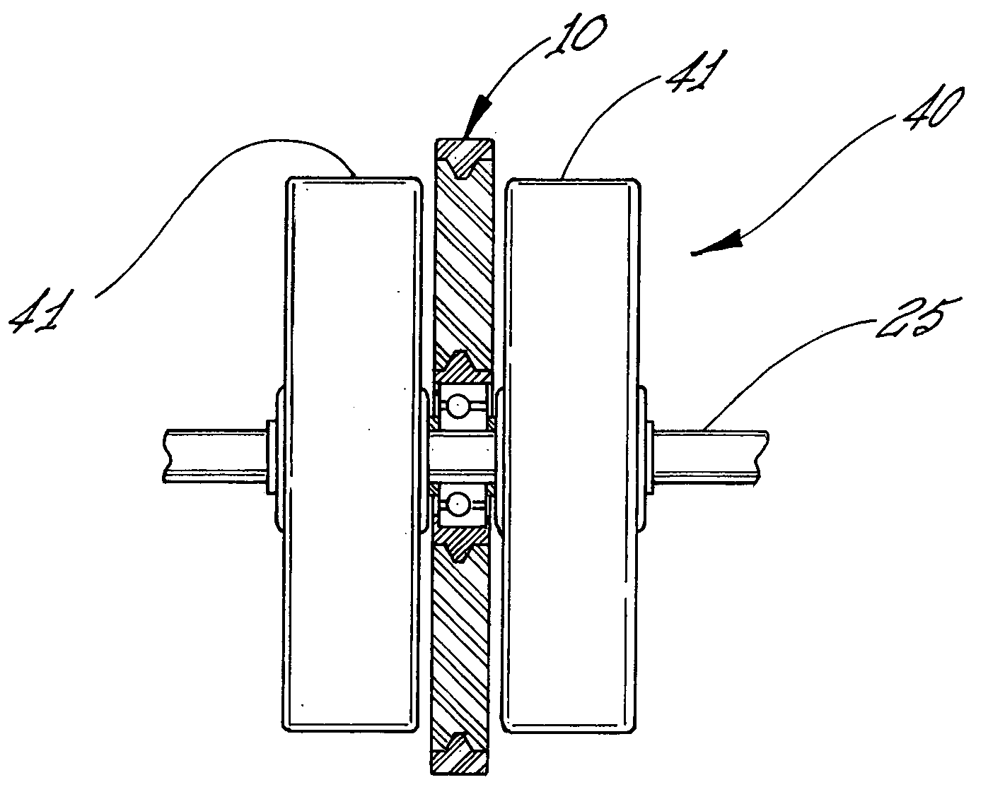
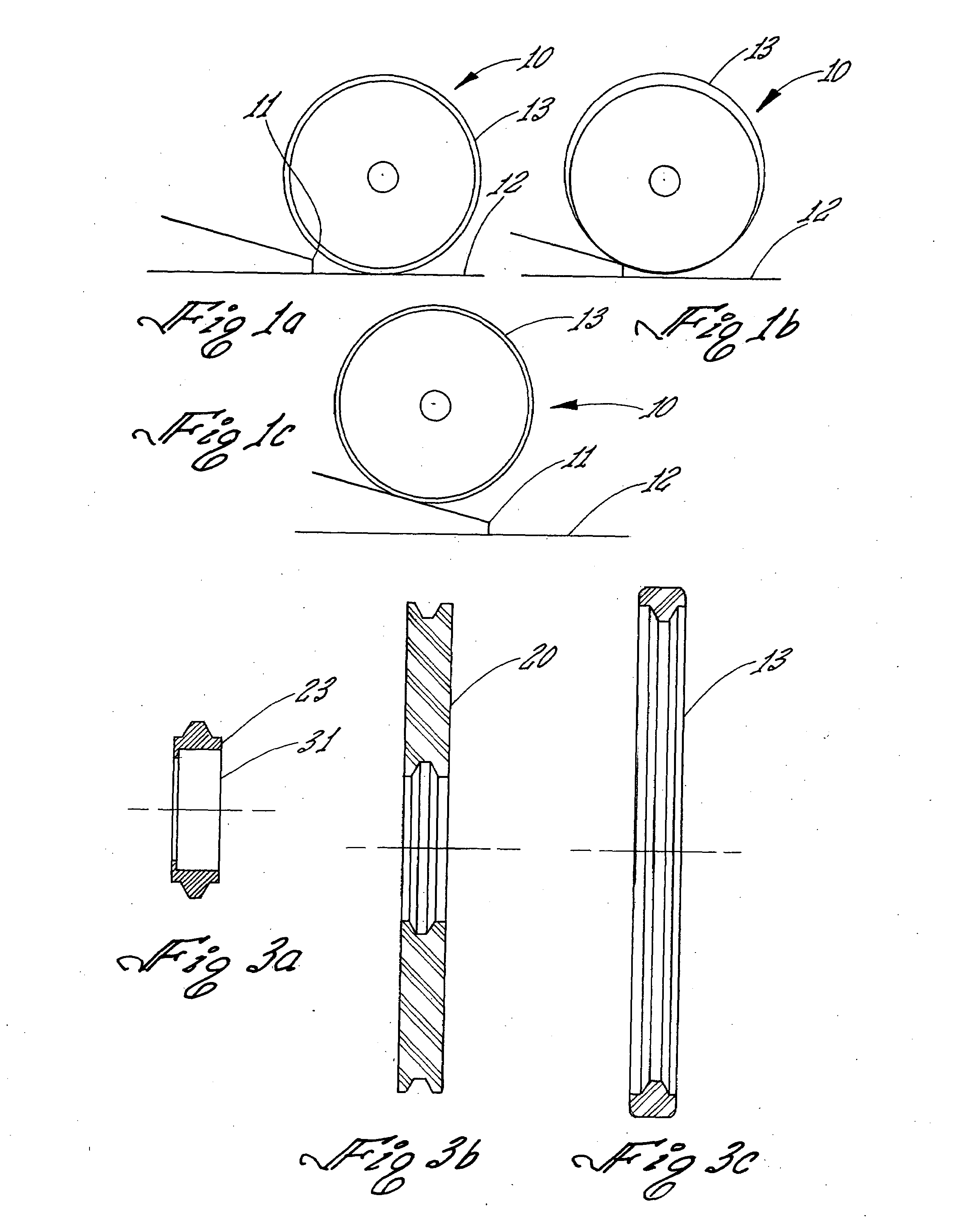
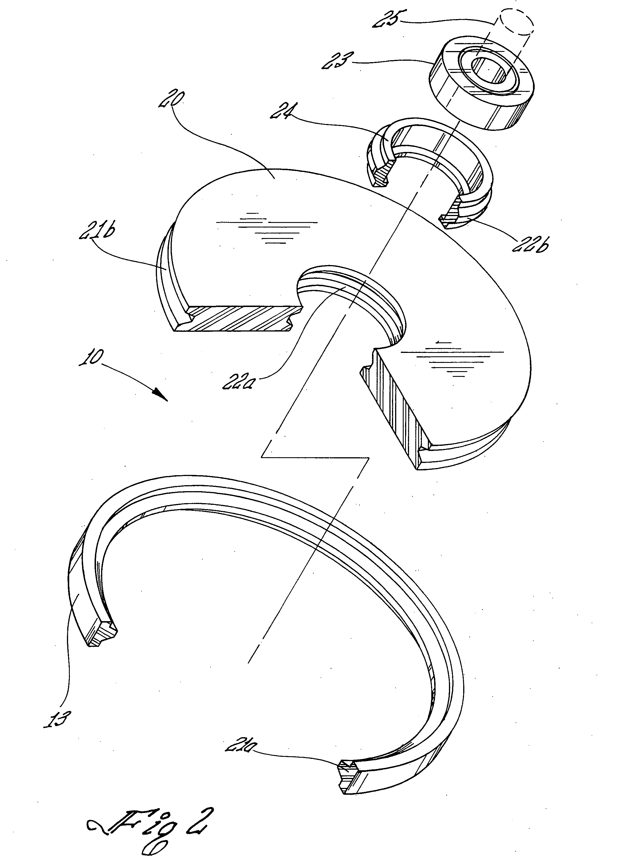
[0029]When a wheelchair is propelled in a forward direction, the front guide wheels are the first part of the wheelchair to encounter a discontinuity in the supporting surface. Such an encounter results in a sudden vertical displacement of the guide wheels, the magnitude of the displacement and the rate of change depending on the speed of the wheelchair and the size of the discontinuity. The sudden change in momentum is transferred to the wheelchair and the passenger. The magnitude of the rate of change in momentum or shock can be reduced by the addition of shock absorbing means to the guide wheel assembly. An example of the effect of shock absorbing means is shown pictorially in FIGS. 1a-1c. FIG. 1a is a schematic drawing showing one of the two guide wheels 10 of a wheelchair (not shown) in accordance with the present invention approaching a shocking event comprising an abrupt discontinuity 11 in the relatively smooth supporting surface 12. FIG. 1b is a schematic drawing showing a ...


PUM


Abstract

A shock absorbing wheel assembly. In a first embodiment, the wheel assembly comprises a rigid hub adapted to be mounted on an axle, a first relatively elastic material concentrically mounted over and affixed to the hub and an annular wheel having a first outer diameter comprised of a second relatively inelastic material overlying and affixed to the outer perimeter of the first relatively elastic material. The first relatively elastic material is preferably a toroid comprised of a closed cell foam. In a second embodiment, the wheel assembly is a compound wheel comprising, in combination, the first embodiment of the wheel assembly wherein the first embodiment is elastically compressible, coaxially mounted adjacent to a relatively noncompressible second wheel having a second outer diameter that is less than the first outer diameter. In the second embodiment, the elastically compressible portion of the compound wheel assembly deforms inwardly when subjected to a shocking event until the outer surface of the second wheel comes into contact with the supporting surface thereby gradually transferring the weight of the wheelchair to the outer surface of both wheels and reducing shock.

Description

BACKGROUND OF THE INVENTION[0001]1. Field of the Invention[0002]The present invention relates to a wheel assembly adapted to absorb shock and, more particularly, a compound shock-absorbing wheel assembly for a wheelchair.[0003]2. Prior Art[0004]Wheelchair manufacturers have attempted to improve the comfort of the wheelchair. One area of ongoing concern is the capability of the wheelchair to exhibit shock absorption characteristics while, at the same time, being easy to propel. A suspension system is incorporated into a wheelchair (or any vehicle) for several reasons. A primary reason is to absorb shocks and thereby insulate the person and / or cargo being carried by the wheelchair / vehicle from shock. For example, during use of a wheelchair, small bumps, depressions or other irregularities on the surface on which the wheelchair is traveling can cause such shocks. Many prior art suspension systems are too expensive and / or too heavy for incorporation into today's lightweight and relative...

Claims


Application Information

Patent Timeline
Patent Type & Authority Applications(United States)
IPC IPC(8): B60B15/26B60B15/04
CPCB60B11/00B60B9/10
Inventor ST. GEORGE, EDWARD
Owner ST GEORGE EDWARD
Why Eureka
Try Eureka