Electroluminescent lighting for a managed-care setting

a technology of electroluminescent lighting and managed care facilities, applied in visible signalling systems, instruments, signalling systems, etc., can solve the problems of inability to find electroluminescent lighting devices that work in combination with equipment used in managed care facilities, high activation voltage and low brightness,

Inactive Publication Date: 2008-05-22
GAYMAR IND
View PDF25 Cites 2 Cited by
  • Summary
  • Abstract
  • Description
  • Claims
  • Application Information

AI Technical Summary

Problems solved by technology

Inorganic EL devices, however, typically suffer from a required high activation voltage and low brightness.
We have, however, been unable to find any disclosure of electroluminescent lighting devices that work in combination with equipment used in managed-care facilities.

Method used


Image

  • Electroluminescent lighting for a managed-care setting
  • Electroluminescent lighting for a managed-care setting

Examples


Embodiment Construction

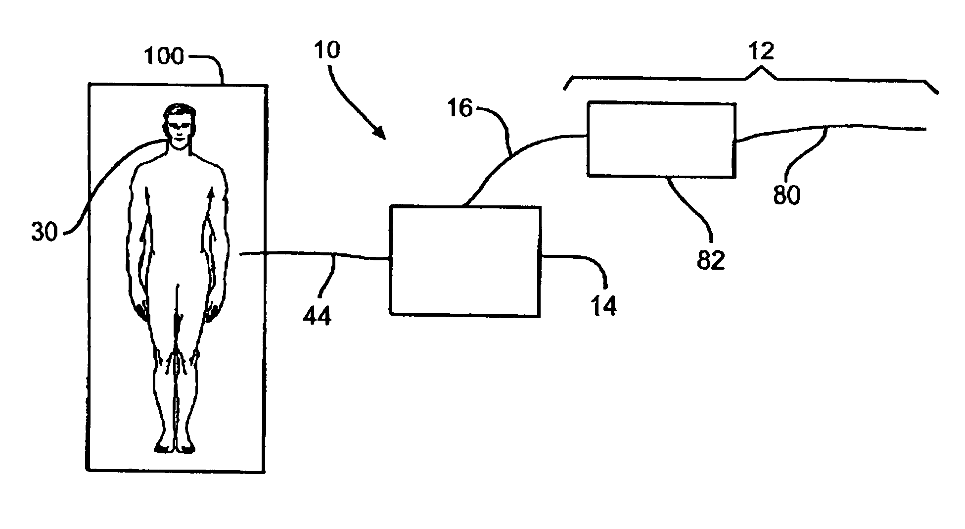
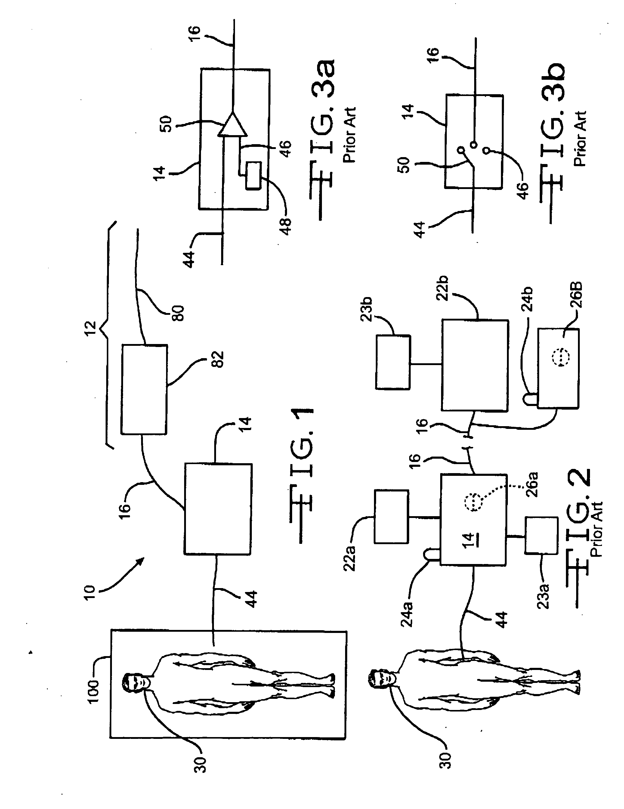
[0018]FIG. 1 illustrates a schematic embodiment of a signaling system 10. The signaling system 10 comprises an electroluminescent lighting device 12 and a managed-care facility equipment 14. Prior to addressing the present invention, the managed-care facility equipment 14 will be discussed in greater detail as to how the equipment is presently being used in today's environment.

[0019]In a managed-care facility, there is the observing entity and the observed mammal. For this application and for readability, we will refer the observing entity as a “nurse” and the observed mammal as a “patient.” Obviously, the description of a nurse and a patient are not to be limiting because the present invention has applications outside the scope of a hospital setting.

[0020]Presently the managed-care facility equipment 14 measures a desired status regarding the patient 30 as illustrated in FIG. 2. That measurement 44 could be any thing that relates to the patient 30.

[0021]The facility equipment 14 ma...


PUM


Abstract

A signaling system having a managed-care facility equipment and a light source are essential components of the present invention. The managed-care facility equipment measures a status of an individual. Based on the measurement of the individual's status in relation to a desired and / or expected measurement parameter, the equipment transmits a status signal that is at least either an alarm status signal or an acceptable status signal. The light source has at least a first flexible electroluminescent filament and receives the status signal. Depending on the status signal received, the light source alters the illumination of the first flexible electroluminescent filament.

Description

FIELD OF THE INVENTION[0001]The present invention is directed to using an electroluminescent lighting device in a managed-care setting. The term managed-care setting includes and is not limited to any place where at least one individual is observed, monitored, cared for and / or supervised. Examples of such managed-care settings include and not limited to hospitals, prisons, nursing homes, elderly care settings, offices, child care centers or anything equivalent thereof.BACKGROUND OF THE INVENTION[0002]There are numerous electroluminescent lighting devices. These devices are disclosed in the following U.S. patents, which are hereby incorporated by reference:U.S. Pat. No.Title6,891,330Mechanically flexible organicelectroluminescent devicewith directional lightemission6,883,931Elongated illumination device6,869,202Lighting apparatus6,851,818Electroluminescent cable andmounting system therefor6,837,591Kitchen appliance with elongatedlight source6,817,731Elongated illumination device6,733...

Claims


Application Information

Patent Timeline
Patent Type & Authority Applications(United States)
IPC IPC(8): G08B23/00
CPCG08B21/04G08B5/36
Inventor CAZZINI, KARL
Owner GAYMAR IND
Why Eureka
Try Eureka