Display device with improved heat dissipation

Inactive Publication Date: 2008-05-22
SAMSUNG SDI CO LTD
View PDF19 Cites 14 Cited by
  • Summary
  • Abstract
  • Description
  • Claims
  • Application Information

AI Technical Summary

Benefits of technology

[0009]A further exemplary embodiment of the present invention includes a plasma display panel using a gas discharge including a chassis base coupled to the display panel to support the display panel, the chassis base having at least one rail extending in a first direction, and at least one reinforcing member formed to straddle the at least one rail. The at least one rail may be integral with the chassis base and may provide a channel between the at least one rail and the chassis base. The rail may have at least one rail hole. Furthermore, the reinforcing member may have a re

Problems solved by technology

The heat generated in the PDP may cause problems in displaying the image.
However,

Method used


Image

  • Display device with improved heat dissipation
  • Display device with improved heat dissipation
  • Display device with improved heat dissipation

Examples


Embodiment Construction

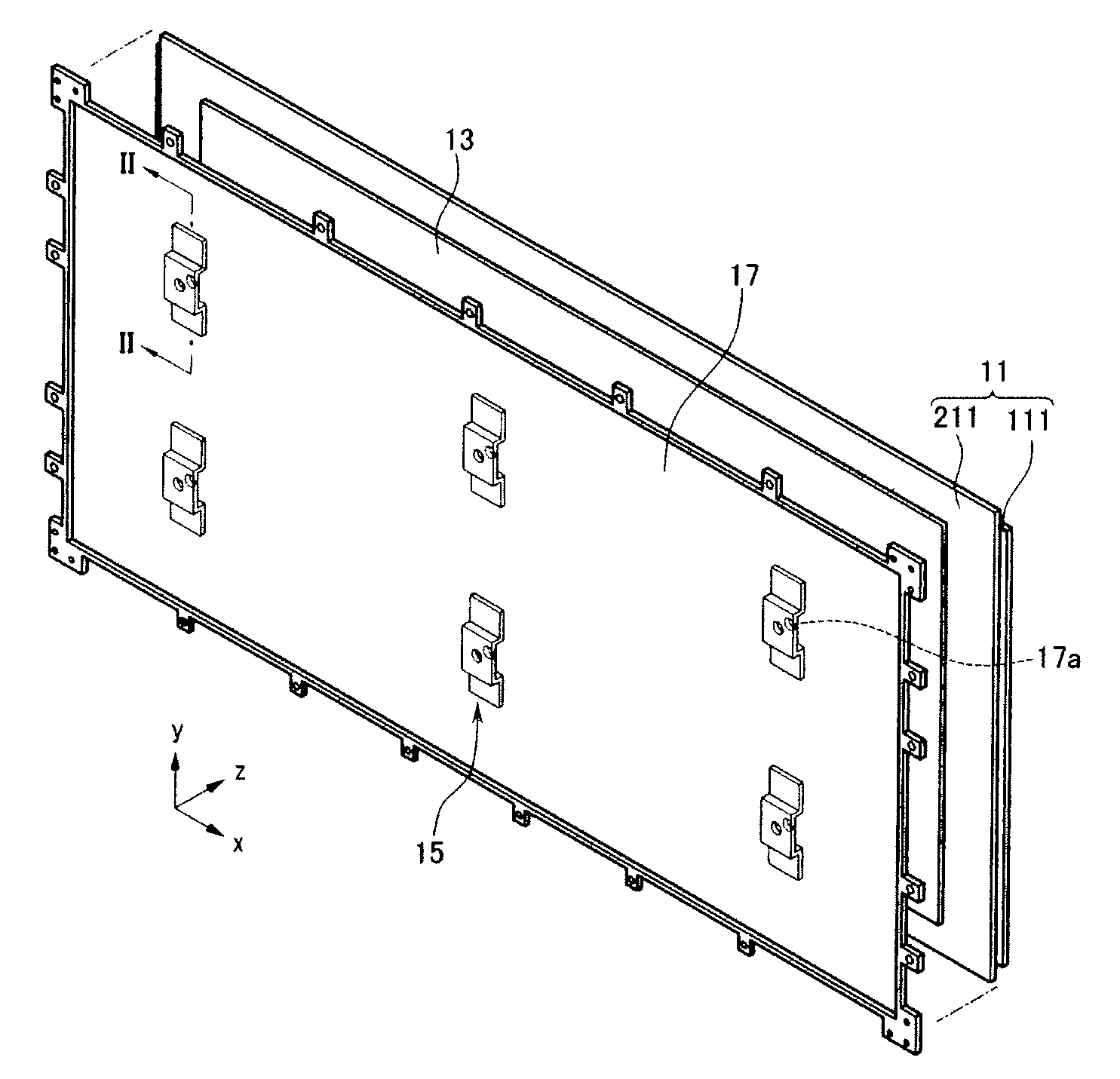
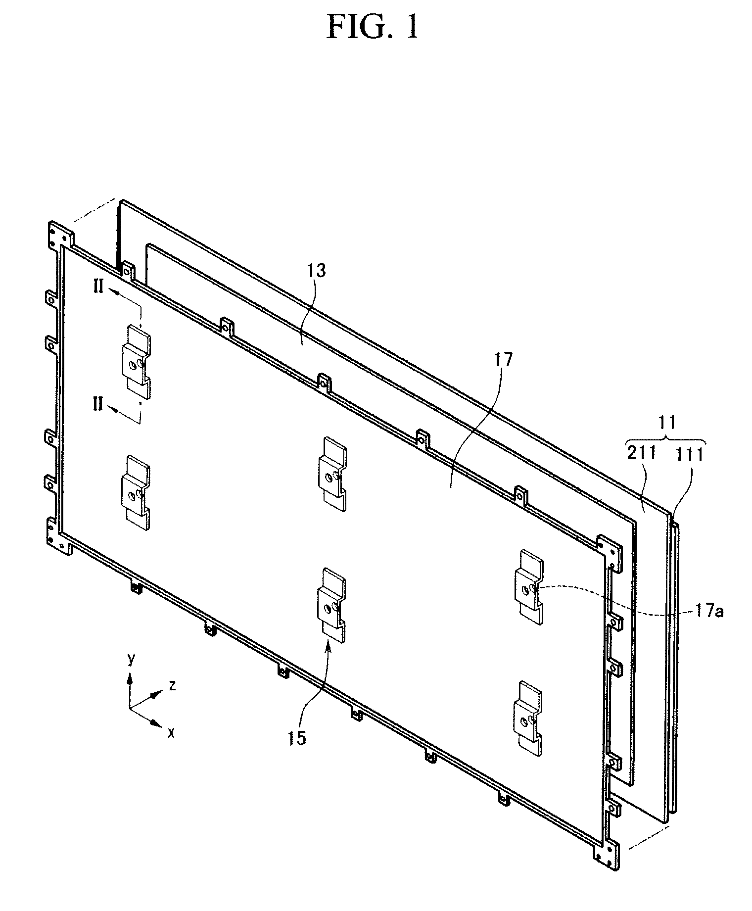
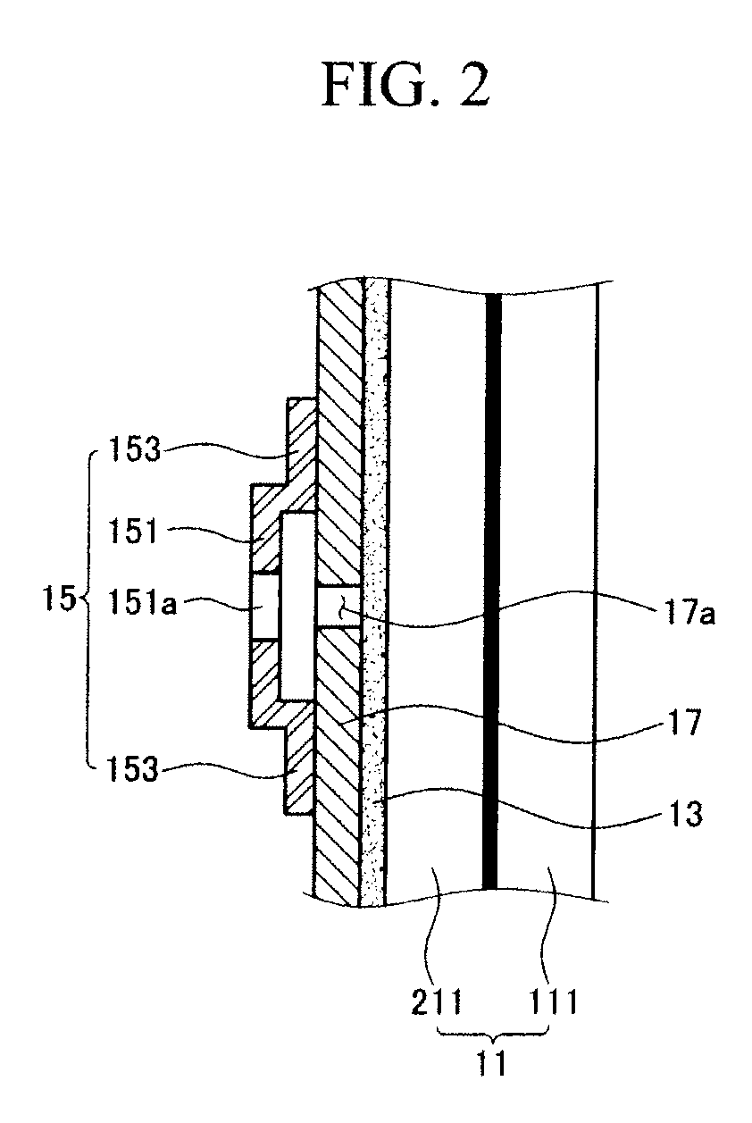
[0017]Referring to FIG. 1, a plasma display device includes a PDP (hereinafter called “panel”) 11 for displaying an image using a gas discharge and a chassis base 17 attached on a first surface of the panel 11. Holes 17a and reinforcing members 15 associated with the respective holes are provided on the chassis base 17.

[0018]A heat dissipation sheet 13 may be interposed between the first surface of the panel 11 and a first surface of the chassis base 17. The heat dissipation sheet 13 conducts and disperses heat generated from the panel 11 in a planar direction (x-y plane direction). The heat dissipation sheet 13 may be a high thermal-conductive material such as an acryl-based material, a graphite-based material, a metal-based material, or a carbon nanotube-based material.

[0019]The panel 11 includes front and rear substrates 111, 211. A space defined between the front and rear substrates 111, 211 is divided to form discharge cells. The discharge cells define respective subpixels each...


PUM


Abstract

A display device comprising a display panel for displaying an image, a chassis base coupled to the display panel to support the display panel, the chassis base having at least one chassis base hole, and at least one reinforcing member formed on the chassis base such that the at least one reinforcing member covers the at least one chassis base hole.

Description

CROSS-REFERENCE TO RELATED APPLICATION[0001]This application claims priority to and the benefit of Korean Patent Application No. 10-2006-0114686, filed in the Korean Intellectual Property Office on Nov. 20, 2006, the entire content of which is incorporated herein by reference.BACKGROUND OF THE INVENTION[0002]1. Field of the Invention[0003]The present invention relates to a display device, and more specifically, to a plasma display device having a plasma display panel (PDP) with improved heat dissipation.[0004]2. Description of Related Art[0005]A plasma display device is one type of flat panel display device that displays an image using plasma created by gas discharge. A conventional plasma display device includes a PDP, a chassis base for supporting the PDP, and a plurality of driving boards mounted on the chassis base. The driving boards are connected to display electrodes or address electrodes disposed in the PDP through a flexible printed circuit (FPC) and a connector.[0006]The d...

Claims


Application Information

Patent Timeline
IPC IPC(8): G06F1/16H05K7/00H05K7/20H05K5/00
CPCG06F1/1601H05K7/20963G06F1/20H01J11/34H05K7/04
Inventor KANG, TAE-KYOUNG
Owner SAMSUNG SDI CO LTD
Why Eureka
Try Eureka