Electrical Connector
- Summary
- Abstract
- Description
- Claims
- Application Information
AI Technical Summary
Benefits of technology
Problems solved by technology
Method used
Image

Examples
Embodiment Construction
[0015]Reference will now be made to the drawings to describe the present invention in detail.
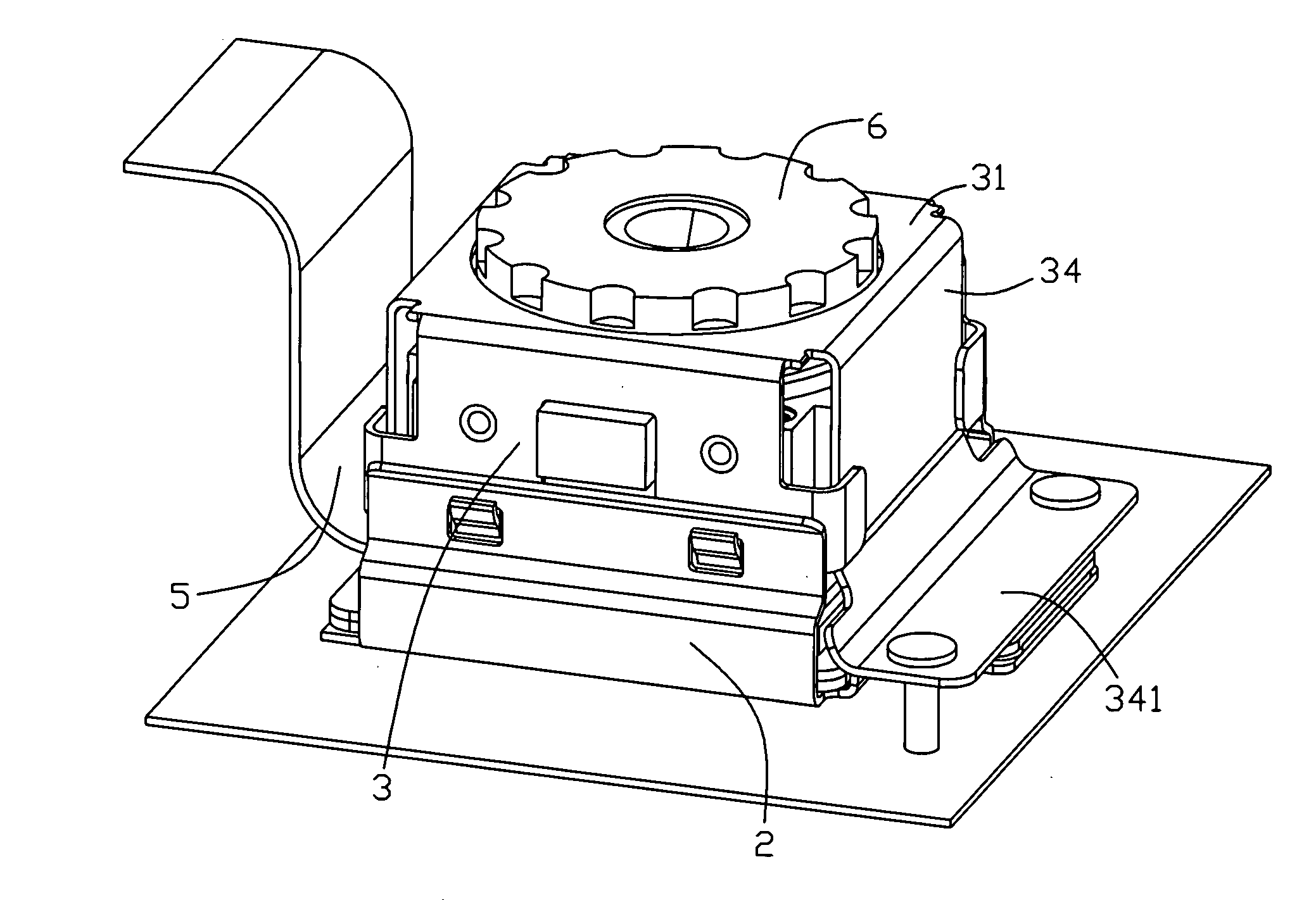
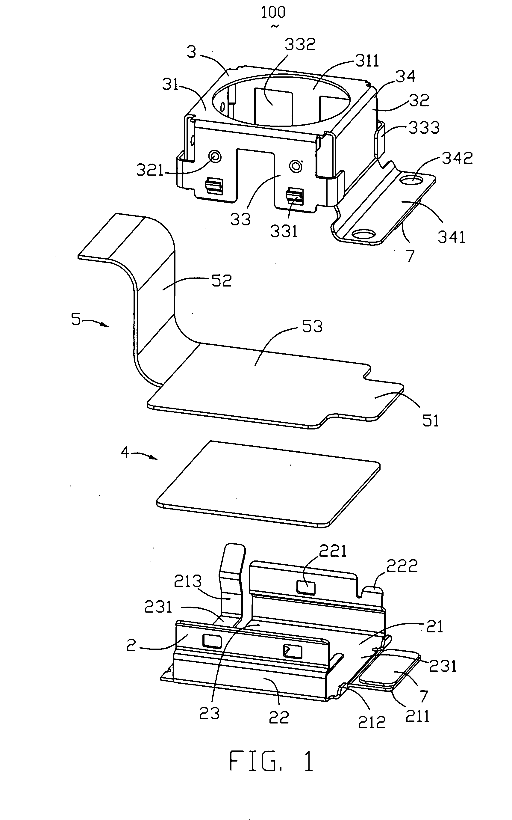
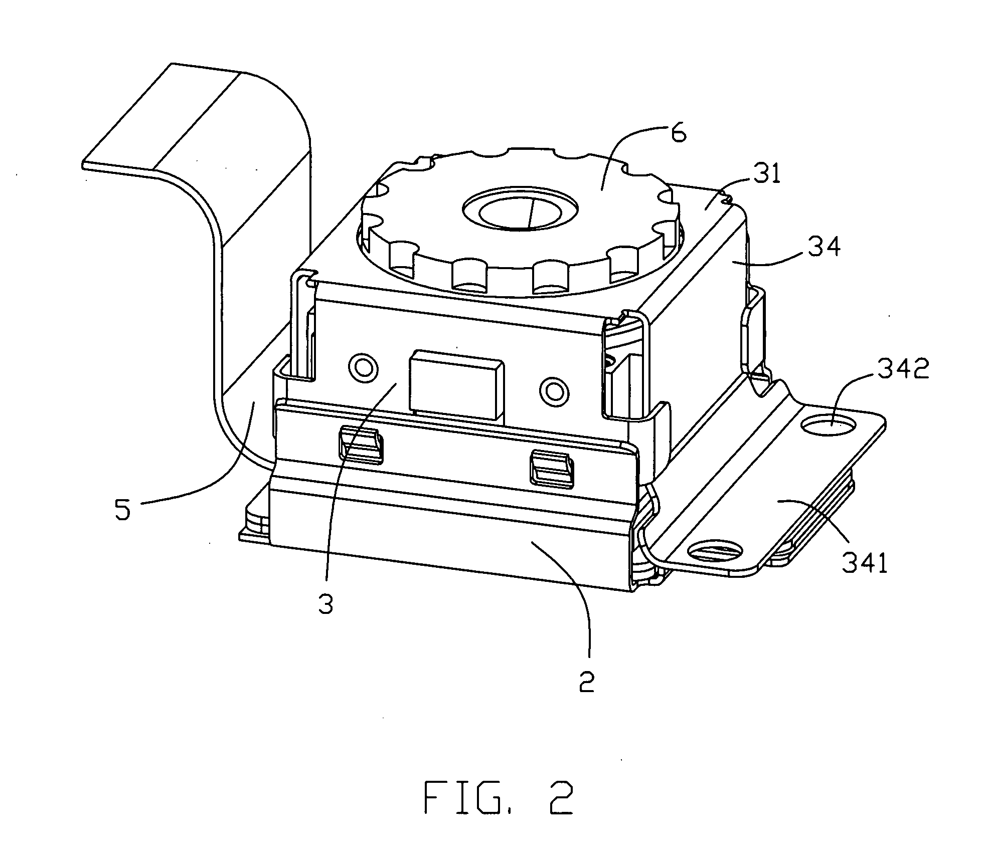
[0016]Referring to FIGS. 1-4, an electrical connector 100 comprises a lower shield 2, an upper shield 3, a support element 4 and a flexible printed circuit 5. The electrical connector 100 is adapted for receiving a camera module 6 therein. In an alternative embodiment, the electrical connector 100 may receive a memory module or likes.
[0017]The lower shield 2 is substantially rectangular case, comprising a bottom wall 21 and two opposite sidewalls 22 extending upwardly from the bottom wall 21 to thereby define a rectangular receiving space 23 therebetween. The receiving space 23 includes a supporting surface (not labeled) for supporting the support element 4 or the flexible printed circuit 5, and two cutouts 231 defined at the opposite ends of the bottom wall 21. A first plate element 211 horizontally extends outwardly from an edge of the bottom wall 21, two tabs 212 adjacent the first plate ...
PUM
 Abstract
Description
Claims
Application Information
 - R&D
- Intellectual Property
- Life Sciences
- Materials
- Tech Scout
- Unparalleled Data Quality
- Higher Quality Content
- 60% Fewer Hallucinations
Browse by: Latest US Patents, China's latest patents, Technical Efficacy Thesaurus, Application Domain, Technology Topic, Popular Technical Reports.
© 2025 PatSnap. All rights reserved.Legal|Privacy policy|Modern Slavery Act Transparency Statement|Sitemap|About US| Contact US: help@patsnap.com