
Roughness scanner

a scanner and roughness technology, applied in the field of roughness scanners, can solve the problems of difficult to remove solvent or flushing medium from the roughness scanner, the measuring results of such a roughness scanner are no longer reliable, and the roughness scanner may at times come into contact with oily workpiece surfaces, etc., to achieve the effect of facilitating cleaning and reducing the sensitivity of the roughness scanner

Active Publication Date: 2008-05-29
CARL MAHR HLDG
View PDF30 Cites 7 Cited by
  • Summary
  • Abstract
  • Description
  • Claims
  • Application Information

AI Technical Summary

Benefits of technology

[0007]Since the opening receiving the scanner needle is open toward the front and / or the rear the cleaning fluid can be admitted to the scanner needle without difficulty and can also be again removed. It is also easily possible to clean the gap formed by the skid around the scanner needle with compressed air.
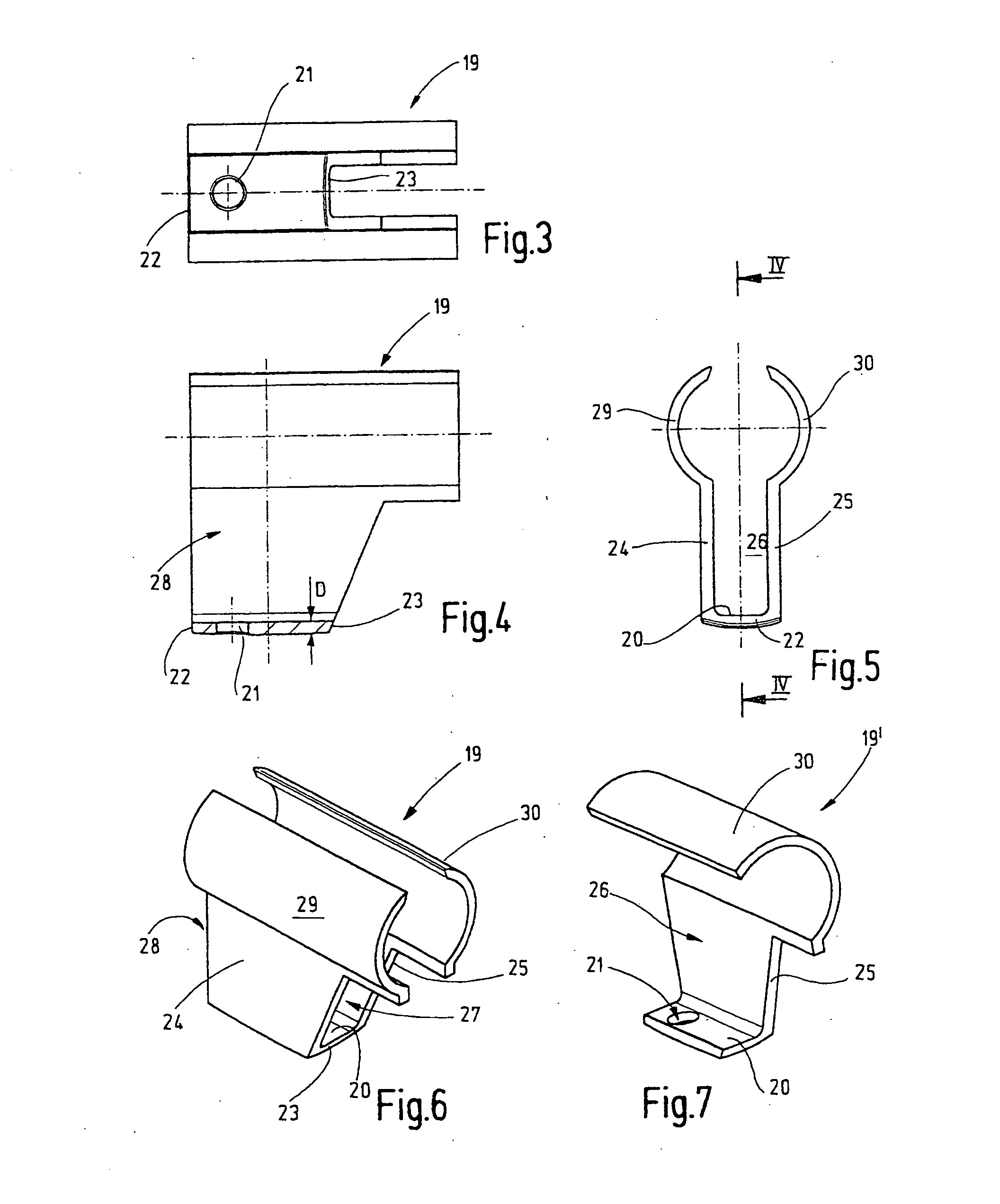
[0010]The plate, which is formed at the skid and though which the scanner needle extends, is preferably slightly arched at it end facing the workpiece. The arch can have a curvature in the direction of movement of the scanner or in a direction transverse to the movement of the scanner. Also, the radii of the curvature may be different. A curvature transverse to the direction of movement makes it possible to hold the roughness scanner at slightly different angles with respect to the workpiece surface. It does not need to be oriented exactly parallel to the workpiece surface. The curvature in the direction of movement is advantageous if concave surface areas such as bare walls are scanned.
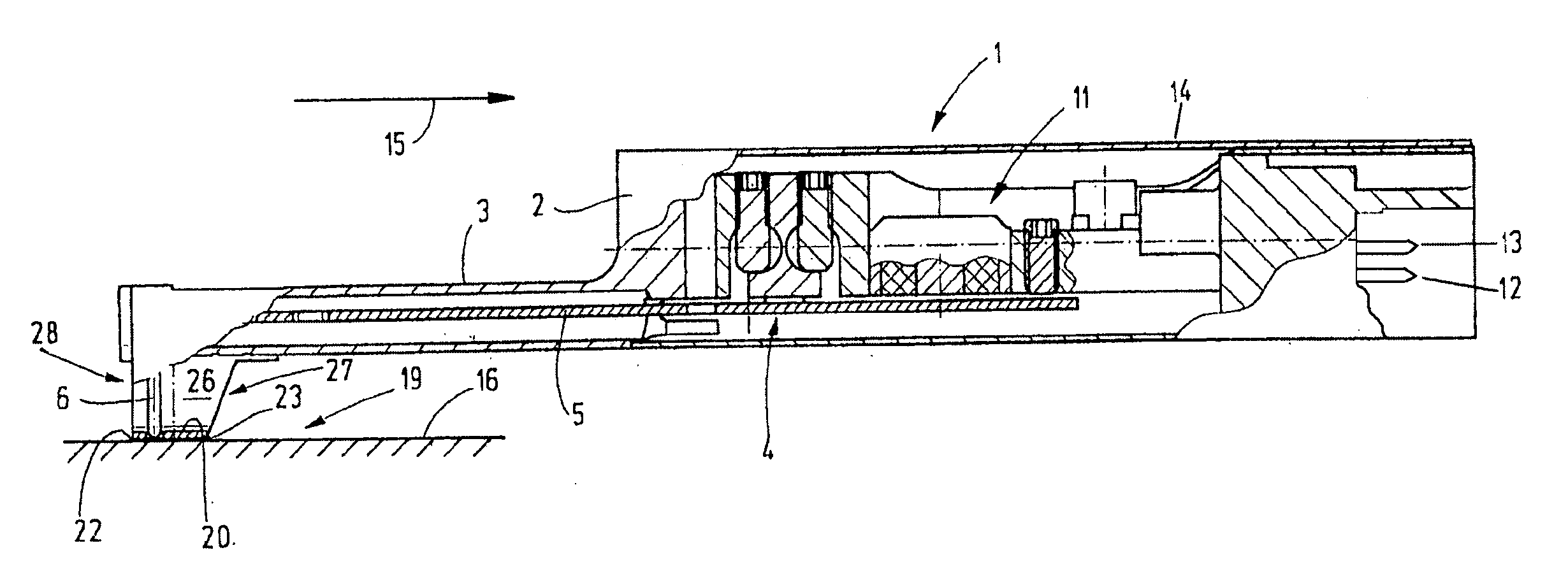
[0011]The plate is connected to a clamp by at least one, but preferably two, support arms which project from the two long edges of the plate. An upper arched section of each arm forces the clamp for attaching the skid carrier. The space present between the two arms is, with respect to the direction of movement, preferably open toward the front as well as toward the rear. The respective opening extends preferably directly to the plate. Fluids which have entered the space between the arms via the opening provided in the plate can therefore freely flow out again. This reduces the soiling sensitivity of the roughness scanner and facilitates the cleaning thereof.

Problems solved by technology

Although it is not in compliance with the measuring specifications, the roughness scanners may at times come into contact with oily workpiece surfaces.
Such problems occur mainly during use in connection with manufacturing equipment.
However, because of its viscosity the oil influences the measurements undesirably, so that the measuring results of such a roughness scanner are no longer reliable.
Furthermore, it is difficult to remove solvent or flushing medium from the roughness scanner.
A visual examination whether the gap around the scanner needle is free from solvents or flushing liquids, washing liquids, oils or similar media, is impossible without magnifier and is even with a magnifier not reliably possible.

Method used


Image

  • Roughness scanner
  • Roughness scanner
  • Roughness scanner

Examples


Embodiment Construction

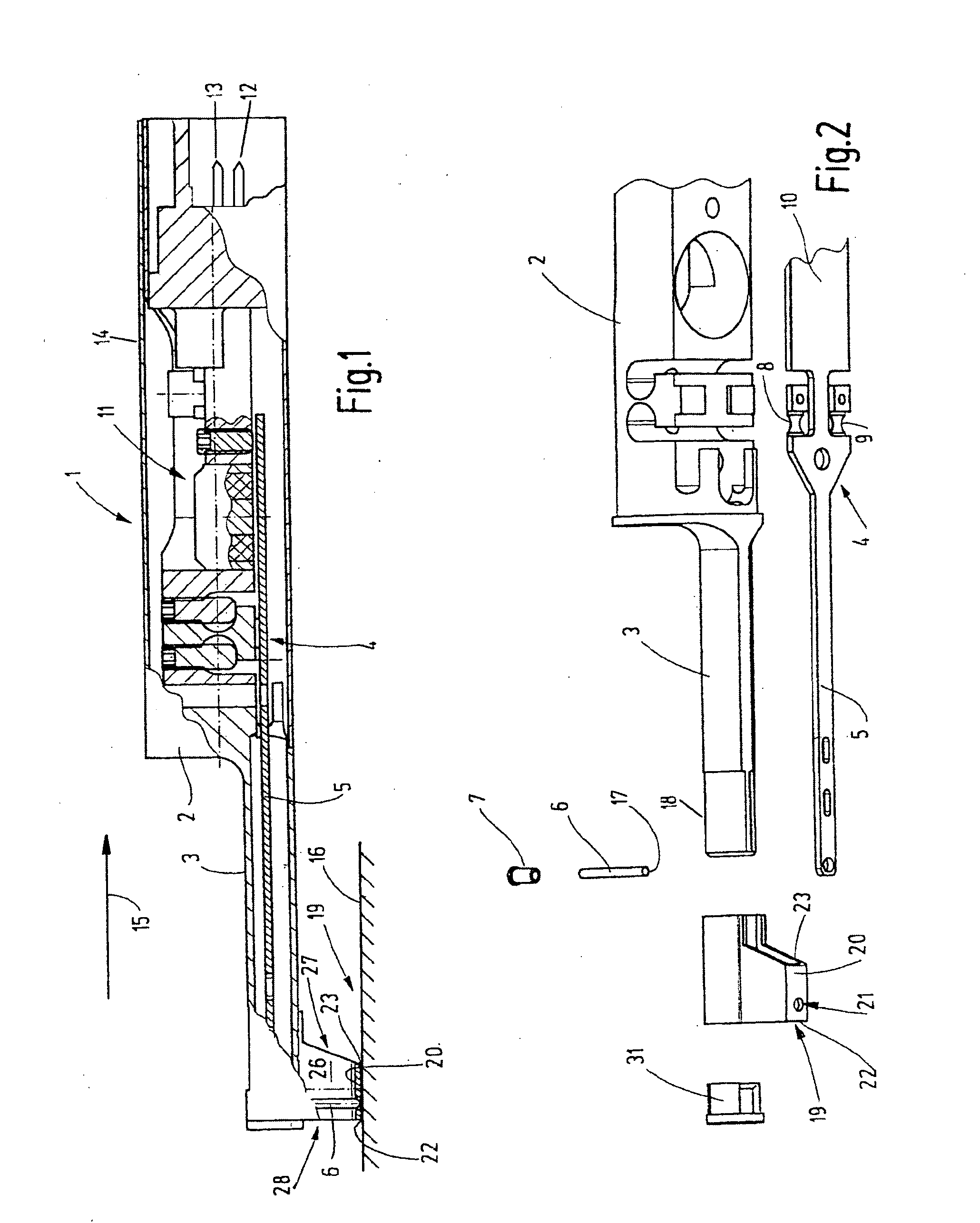
[0020]FIG. 1 shows a roughness scanner 1 having a base body 2 provided with a skid carrier 3 in the form of a tube which projects from the base body 2. In place of a tubular skid carrier 3, a skid carrier in the form of a U-profile may be used. Furthermore, it may be in the form of an oval tube, a circular tube, a rectangular tube or of similar shape. Through the skid carrier 3, a lever arm 5 extends which is part of a scanning arm 4 and which carries at its free end a scanning needle 6. The scanning needle 6 is held in a socket 7 which supports it at the end of the lever arm 5.

[0021]The scanning arm 4 is movably supported by the base body 2 via spring joints 8, 9 (FIG. 2) and includes a second lever arm 10 which cooperates with a sensor 11 for picking up movements and position changes of the scanning arm 4. Signals of the sensor 11 can be taken up from the outside via plug-in contact pins 12, 13.

[0022]The roughness scanner 1 preferably has a cylindrical outer shape. It is accommoda...


PUM


Abstract

In a roughness scanner comprising a scanning arm with a scanning needle mounted at one end thereof, a skid carrier having an end supporting a skid with the scanning arm extending along the skid carrier in spaced relationship therefrom, the skid has at one side a guide plate including an opening through which the scanning needle extends and a space formed above the guide plate which space is open at least at one side thereof down to the guide plate, so that any liquid collected by the needle and moving upward into the space above the guide plate can flow again out of that space.

Description

CROSS-REFERENCE TO RELATED APPLICATION[0001]This is a continuation-in-part application of pending international application PCT / EP2006 / 007053 filed Jul. 18, 2006 and claiming the priority of German Application No. 10 2005 035 786.5 filed Jul. 27, 2005.BACKGROUND OF THE INVENTION[0002]The invention resides in a roughness scanner particularly for industrial applications, but also for laboratory use.[0003]Roughness scanners are used to determine the roughness of a surface. To this end, the roughness scanner includes a skid of a size of a few millimeters which is in contact with the workpiece. A very fine scanner needle extends through an opening in the skid and into contact with the workpiece surface. The vibrations of the scanner needle caused by the roughness of the surface during the skid over the workpiece are picked up just like in a record player and converted into electrical signals and are evaluated for determining a characteristic roughness value.[0004]The scanner needle and t...

Claims


Application Information

Patent Timeline
Patent Type & Authority Applications(United States)
IPC IPC(8): G01B5/28
CPCG01B5/28
Inventor DORRER, PEGGYLUDWIG, JOSEFZIEGENBEIN, RAINER
Owner CARL MAHR HLDG
Learn More