Solenoid control valve

a solenoid control valve and solenoid technology, applied in the direction of valve operating means/releasing devices, mechanical equipment, transportation and packaging, etc., can solve the problems of contamination sensitivity, hindering consistency and stability in clutch control, and conventional design of solenoid combined with spool valve to control hydraulic actuation of clutches, etc., to reduce contamination sensitivity, reduce contamination sensitivity, and repeatable

Inactive Publication Date: 2005-06-21
BORGWARNER INC
View PDF9 Cites 20 Cited by
  • Summary
  • Abstract
  • Description
  • Claims
  • Application Information

AI Technical Summary

Benefits of technology

[0010]Utilizing the construction of the present invention results in precise output pressure stability control under varying temperature, source pressures, output flow demands and commanded control pressures in a contaminated hydraulic fluid media typical of automotive transmission applications. It provides fast, repeatable and stable output pressure responses. The system has low output pressure histeresis and reduced contamination sensitivity. The system also provides high output flow capacities and has low output pressure sensitivity to varying source pressure in the pressure regulating range.

Problems solved by technology

Conventional designs of a solenoid combined with a spool valve to control hydraulic actuation of a clutch were found to be lacking.
This caused overshooting of target control movements that can hinder consistency and stability in clutch control.
Additionally, other known designs included contamination sensitivity due to extremely small dampening pilot ports.
While such orifices have successfully demonstrated their use in cleaner environments, in the environment of a manual transmission clutch small control orifices were problematic due to the minute amounts of contaminants in the transmission fluid.

Method used


Image

  • Solenoid control valve
  • Solenoid control valve
  • Solenoid control valve

Examples


Embodiment Construction

[0018]The following description of the embodiment(s) is merely exemplary in nature and is in no way intended to limit the invention, its application, or uses.

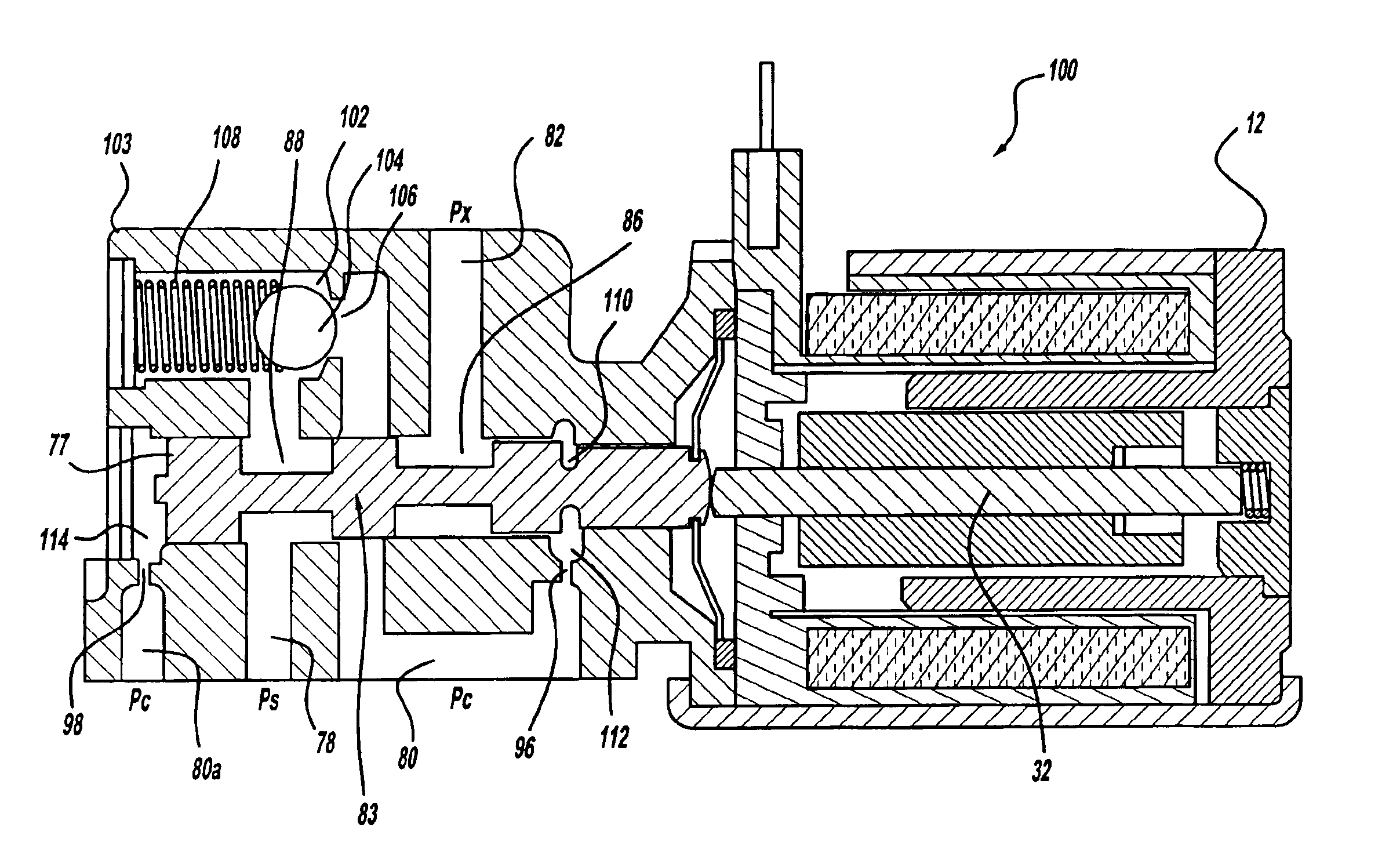
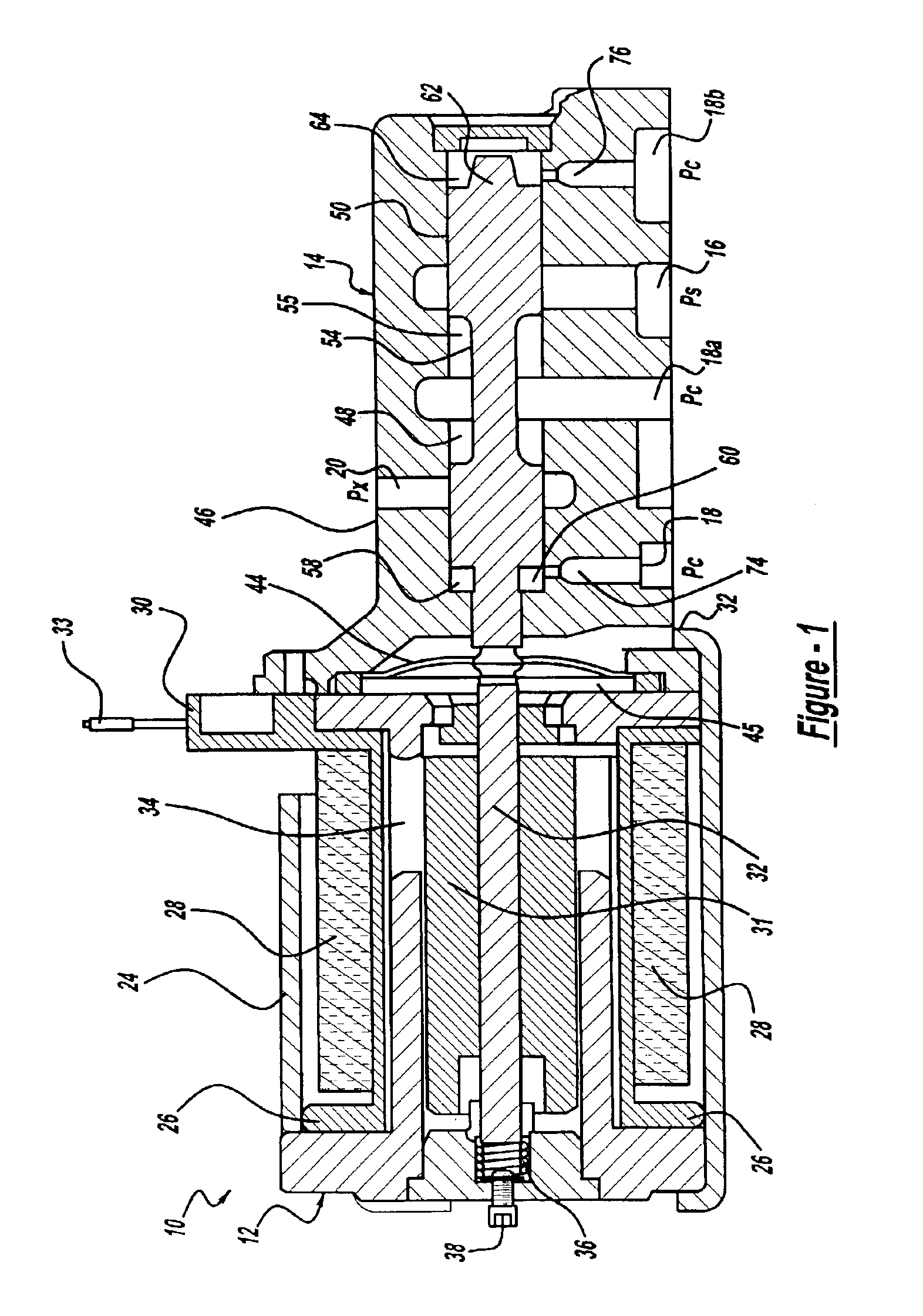
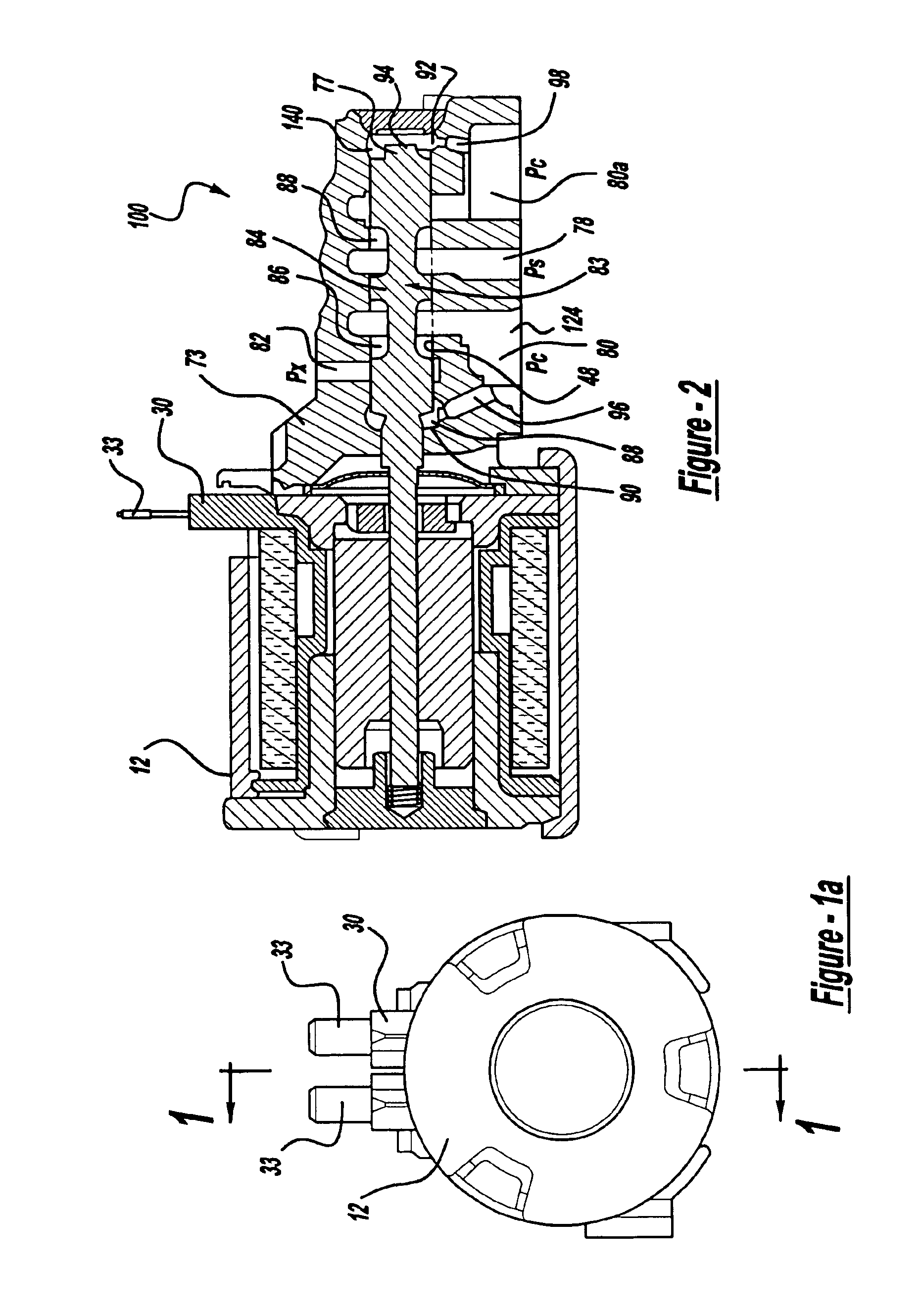
[0019]FIG. 1 depicts a cross-sectional view of a valve 10 in accordance with the teachings of the present invention. The valve 10 as shown and described herein has an electronically controlled solenoid 12 for actuating a spool valve 14 (i.e., hydraulic control valve) to control hydraulic fluid pressure between a supply passage 16, a control passage 18, 18a, 18b, and an exhaust passage 20.

[0020]The solenoid 12 has a housing 24 enclosing a bobbin 26. The bobbin 26 has a primary electromagnetic coil 28 wound thereon. A terminal 30 connects with the electromagnetic coil 28 and to ground. Terminal 30 receives a continuous variable, digital control signal from a primary driver (not shown).

[0021]Accordingly, electromagnetic coil 28 is independently controlled by respective continuous variable, digital control signals. Referring to FIG...


PUM


Abstract

A solenoid control valve for use in actuation of a manual hydraulic clutch in a vehicle. The solenoid control valve has an electronically operated solenoid with armature and actuator rod displaced through a channel in the solenoid. A spool valve has a valve body that is coupled at one end to the solenoid. A spool is slidably disposed in the control channel. A first and second dampener chambers are located at the two ends of the spool. The dampeners function to improve the stability in the control system and balance the transient flow forces of the hydraulic fluid as it moves through the valve member. The spool also has a control portion is located between the first end and the second end of the spool. The control portion allows the control portion to communicate with a supply, control and exhaust passages in the valve body.

Description

CROSS-REFERENCE TO RELATED APPLICATIONS[0001]This application claims benefit of U.S. Provisional Application No. 60 / 384,997, filed Jun. 3, 2002.FIELD OF THE INVENTION[0002]The present invention relates to an apparatus and method for calibrating a solenoid controlled spool valve. More particularly, the present invention relates to a solenoid controlled spool valve useful for actuating a hydraulic clutch of a manual transmission for a vehicle.BACKGROUND OF THE INVENTION[0003]It is desirable in motor vehicles to provide a manually shifted transmission where clutching is accomplished by a hydraulically operated dutch rather than a manually actuated foot pedal type clutch. Ideally such a clutch could be coupled with engine sensors to provide desirable features found in automatic transmissions, such as holding the vehicle on hills while allowing manual shifting of the clutch.[0004]Conventional designs of a solenoid combined with a spool valve to control hydraulic actuation of a clutch wer...

Claims


Application Information

Patent Timeline
Patent Type & Authority Patents(United States)
IPC IPC(8): F16D29/00F16K31/06F16D48/00F16D27/00F16D48/02F16D48/06
CPCF16D25/14F16D28/00F16K31/0613F16D48/02F16D48/066F16D29/00F16D2048/0221F16D2500/10412F16D2500/1082F16D2500/70406F16D2500/7041Y10T137/86622Y10T137/8671
Inventor HOLMES, GARRETT R.TAMBA, RICHARD T.
Owner BORGWARNER INC
Why Eureka
Try Eureka