
Numerical control hydraulic system of switch reluctance motor pump

A switched reluctance motor, hydraulic system technology, applied in mechanical equipment, fluid pressure actuation devices, servo motors, etc., can solve the complex speed regulation and torque control, low efficiency of electro-hydraulic servo system, starting and overload torque Small and other problems, to achieve the effect of flexible motor control, good development and application prospects, and elimination of throttling losses

Inactive Publication Date: 2008-06-18
SHANDONG KEHUI POWER AUTOMATION
View PDF0 Cites 1 Cited by
  • Summary
  • Abstract
  • Description
  • Claims
  • Application Information

AI Technical Summary

Problems solved by technology

The existing problems are: the servo system is particularly sensitive to liquid pollution; the electro-hydraulic servo system requires a pumping station system to provide a constant pressure liquid source; the load pressure provided by the servo valve of the electro-hydraulic servo system is only 2 / 3 of the pressure of the liquid source at most. Serious waste of energy in the system; due to the low efficiency of the electro-hydraulic servo system, the temperature of the system liquid rises, so the system needs to be equipped with a cooling device, resulting in increased system size and complexity, and increased costs
The valveless electro-hydraulic servo system has the following forms: AC servo motor plus quantitative pump, AC asynchronous motor frequency conversion speed regulation plus quantitative hydraulic pump, AC asynchronous motor plus variable pump, etc.; due to the large starting current of the motor itself, starting and overload Small torque, complex speed regulation and torque control, unsatisfactory speed regulation performance, waste of energy and other defects, it is difficult to popularize and use

Method used


Image

  • Numerical control hydraulic system of switch reluctance motor pump
  • Numerical control hydraulic system of switch reluctance motor pump
  • Numerical control hydraulic system of switch reluctance motor pump

Examples


Embodiment Construction

[0019] The present invention will be further described below in conjunction with accompanying drawing:

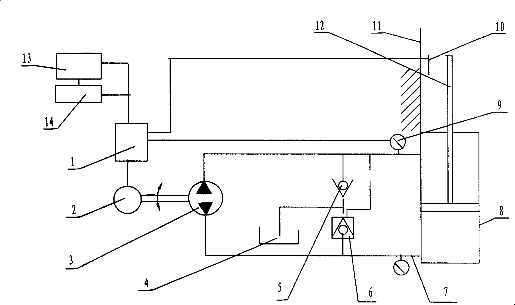
[0020] refer to figure 1 :

[0021] The motor controller is connected to the switched reluctance motor, the switched reluctance motor is connected to the hydraulic pump, the hydraulic pump is connected to the hydraulic cylinder through the hydraulic pipeline system, the pressure sensor is set on the pipeline, and the displacement sensor is set on the fuselage, the output signals of the pressure sensor and the displacement sensor The motor controller is connected, and the external port of the motor controller 1 is provided with a keyboard 14 and a display 13 .

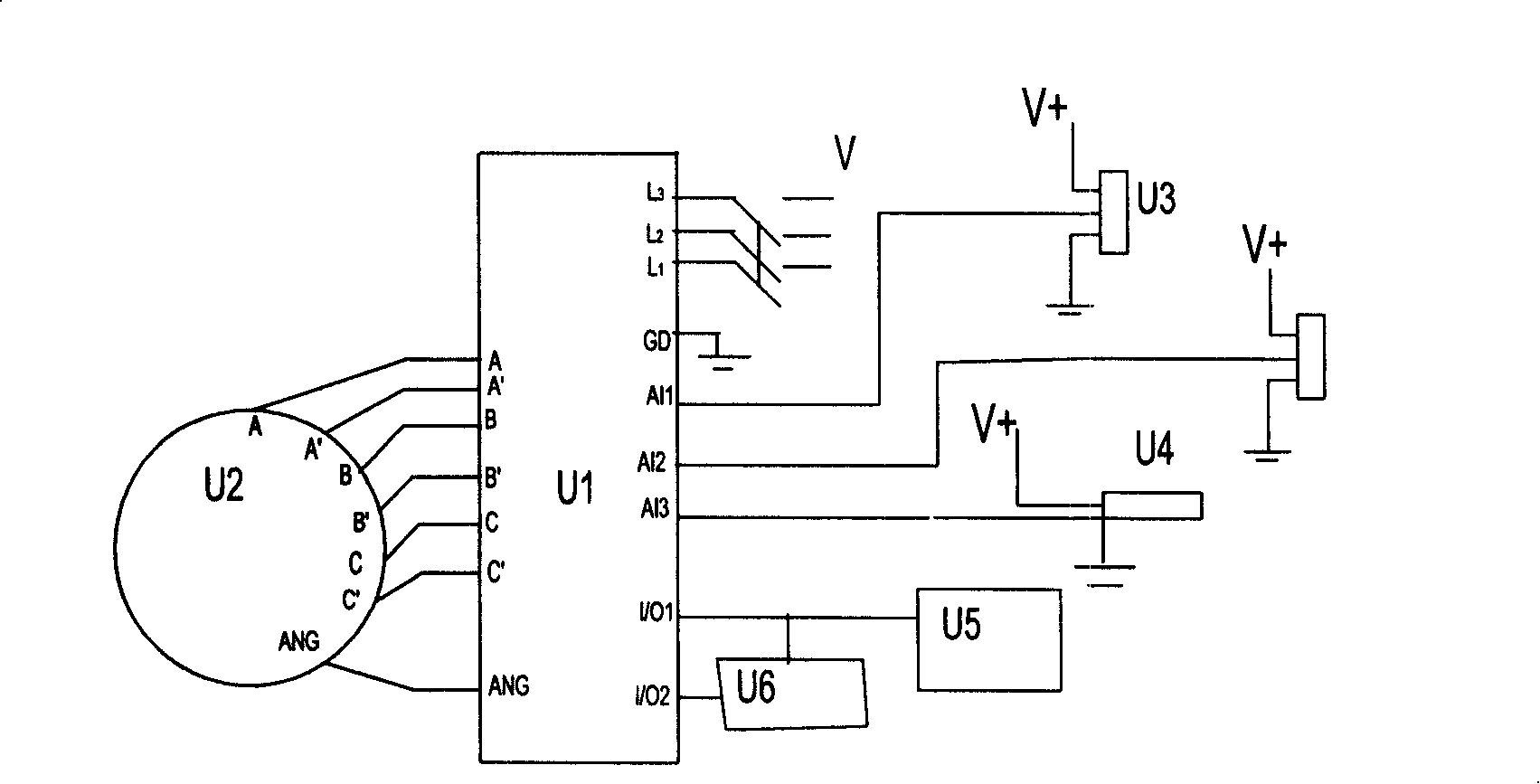
[0022] refer to figure 2 :

[0023] The ports A, A', B, B', C, C' and ANG of the switched reluctance motor U2 are respectively connected to the ports A, A', B, B', C, C' and ANG of the motor controller U1. The L1, L2, L3 ports of the controller U1 are connected to the power supply, two pressure sensors U3, and t...


PUM


Abstract

A numerical control hydraulic system of a switched reluctance motor pump belongs to the filed of the hydraulic transmission and the hydraulic machinery. The invention is characterized in that the invention comprises a hydraulic system and a reversible stepless speed regulating system which are connected with each other. Compared with the prior art, the invention realizes speed regulating, direction changing, numerical control of pressure and displacement, which can simplify the structure of the hydraulic system greatly and eliminate the throttling loss in the system. Meanwhile, the invention has the advantages of simple structure, credible work, strong mechanical strength, high efficiency, energy saving, high speed regulating precision, small start electrical current and frequent positive inversion operation, which can realize the high efficient operation in the broad speed regulating range. The invention is applicable to transport machine, forging machine, metallurgy machine, molding machine, oil press, injection molding machine, die casting machine, rolling mill, pressurizer, etc.

Description

technical field [0001] The invention relates to a numerically controlled hydraulic system of a switched reluctance motor pump, which belongs to the field of hydraulic transmission and hydraulic machinery. Background technique [0002] At present, most hydraulic systems capable of numerical control use electro-hydraulic servo systems, which are mainly composed of electronic and electrical components, electro-hydraulic servo valves, hydraulic actuators, feedback detection components and control objects. The existing problems are: the servo system is particularly sensitive to liquid pollution; the electro-hydraulic servo system requires a pumping station system to provide a constant pressure liquid source; the maximum load pressure provided by the servo valve of the electro-hydraulic servo system is only 2 / 3 of the pressure of the liquid source, The energy waste of the system is serious; due to the low efficiency of the electro-hydraulic servo system, the temperature of the sys...

Claims


Application Information

Patent Timeline
Patent Type & Authority Applications(China)
IPC IPC(8): F15B11/02F15B11/08
Inventor 赵婷婷贾明全徐丙垠
Owner SHANDONG KEHUI POWER AUTOMATION
Learn More