Collision Detection Device and Method of Manufacturing the Same

a technology of collision detection and manufacturing method, which is applied in the direction of bumpers, instruments, pedestrian/occupant safety arrangements, etc., can solve the problems of restricting the separation of mold members from load detection members, and achieve the effect of enhancing the joint strength between different components and simplifying manufactur

Inactive Publication Date: 2008-05-29
DENSO CORP +1
View PDF15 Cites 23 Cited by
  • Summary
  • Abstract
  • Description
  • Claims
  • Application Information

AI Technical Summary

Benefits of technology

[0023]Because the mold member, the attachment member and the load detection member are integrated with each other by molding, the joining strength between different components can be heightened. Accordingly, detachment of the components from each other can be restricted even when the impact due to the collision is relatively large.
[0024]In this case, not only the load detection member but also the concave-convex member can be fixed by the mold member. Thus, the manufacture is simplified as compared with the case where the concave-convex member is mounted in a process different from the molding process.

Problems solved by technology

Thus, a detachment of the mold member from the load detection member can be restricted even when the impact due to the collision is relatively large.

Method used


Image

  • Collision Detection Device and Method of Manufacturing the Same
  • Collision Detection Device and Method of Manufacturing the Same
  • Collision Detection Device and Method of Manufacturing the Same

Examples


first embodiment

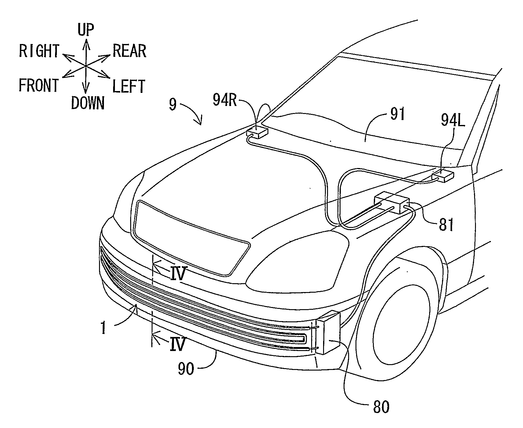
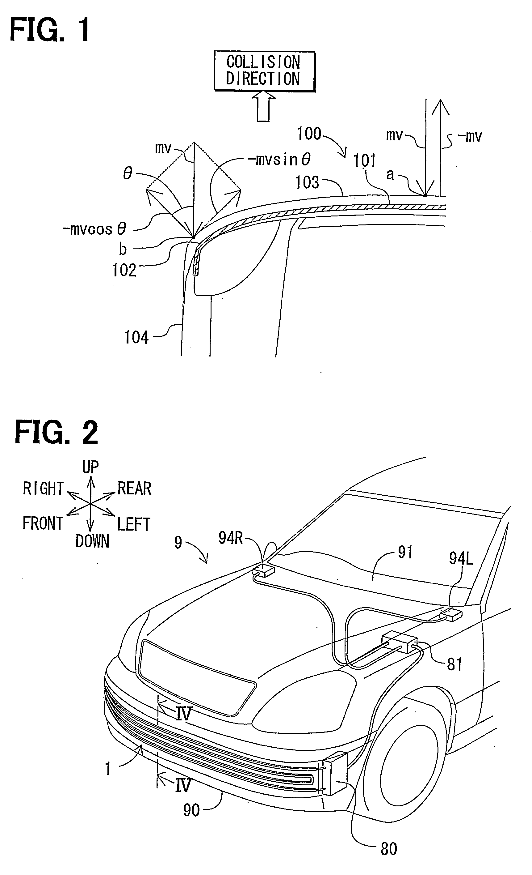
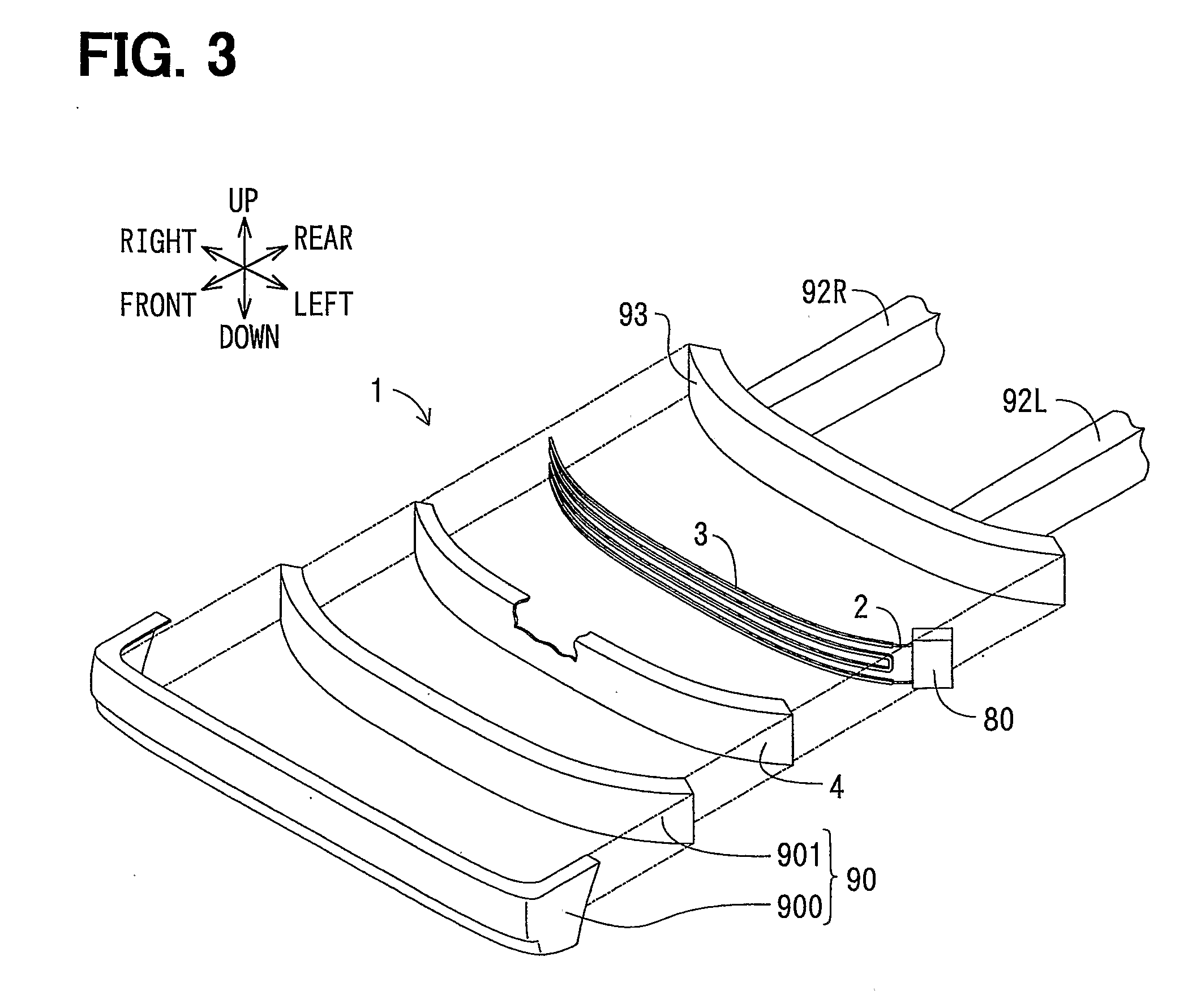
[0040]A collision detection device 1 according to a first embodiment of the present invention will be described with reference to FIGS. 2-11. As shown in FIG. 2, the collision detection device 1 is suitably used for a vehicle 9. The collision detection device 1 can be mounted, for example, in a front bumper 90 of the vehicle 9 and extend in a vehicle right-left direction. A left end and a right end of the collision detection device 1 are respectively bent rearward to a left side and a right side of the vehicle 9.

[0041]The up-down direction, the right-left direction and the front-rear direction indicated in figures respectively correspond to the vehicle up-down direction, the vehicle right-left direction (i.e., vehicle width direction) and the vehicle front-rear direction, which are defined according to the traveling direction of the vehicle 9 as a criterion.

[0042]The collision detection device 1 is connected with a detection circuit 80, which is connected with an airbag ECU 81 (elec...

second embodiment

[0079]A second embodiment of the present invention will be described according to FIGS. 12-14. According to the second embodiment, an up-down direction width of a center portion (of the vehicle width direction) of the mold member 3 is set larger than those of two end portions (of the vehicle width direction) of the mold member 3. Moreover, the opening of the load transmission member 4 is provided with the optical fiber member 2 therein going-returning once in the vehicle width direction. Those are different from the above-described first embodiment.

[0080]As shown in FIG. 12, the optical fiber member 2 (being bend-typed load detection member) includes a frontal portion 2a and two incline portions 2b arranged respectively at the right side and the left side of the frontal portion 2a. The frontal portion 2a extends in the vehicle width direction to be perpendicular to the collision direction (e.g., vehicle front-rear direction). In this case, the frontal portion 2a faces the vehicle fr...

third embodiment

[0087]According to a third embodiment of the present invention, the concave-convex member 5 is arranged between the optical fiber member 2 and the load transmission member 4, which is different from the above-described first and second embodiments.

[0088]As shown in FIG. 15, the concave-convex member 5 is positioned between the rear surface of the load transmission member 4 and the front surface of the optical fiber member 2. The protrusion portions 50 (not shown in FIG. 15) of the concave-convex member 5 contact the clad portion 21 of the optical fiber member 2. The collision detection device 1 according to the second embodiment has the same effects with those described in the first embodiment.

Other Embodiments

[0089]Although the present invention has been fully described in connection with the preferred embodiments thereof with reference to the accompanying drawings, it is to be noted that various changes and modifications will become apparent to those skilled in the art.

[0090]In th...


PUM

PropertyMeasurementUnit
impact energyaaaaaaaaaa
resilient deformationaaaaaaaaaa
transparentaaaaaaaaaa

Abstract

A collision detection device is provided with a load detection member 2 for detecting a collision load in a collision, and a mold member 3 which is molded to be integral with the load detection member 2. The mold member 3 covers at least the surface of a collision side of the load detection member 2, to absorb at least a part of impact energy in the collision by a resilient deformation of the mold member 3. Thus, the collision detection device is substantially resistant to an impact in the collision, while being simply manufactured.

Description

TECHNICAL FIELD[0001]The present invention relates to a collision detection device for detecting a collision load, and a method of manufacturing the same.BACKGROUND ART[0002]Referring to JP-7-190732A, for example, a vehicle is provided with a collision detection sensor (collision detection device) having an optical fiber member. The optical fiber member is attached to a front bumper of the vehicle, and protrudes to an outer side of the front bumper. The optical fiber member is provided with a light-emitting member and a light-receiving member which are respectively arranged at two longitudinal-direction ends of the optical fiber member. When the vehicle collides with an obstacle, a collision load will be exerted at the optical fiber member, so that the optical fiber member is deformed to cause a variation of a light-receiving amount of the light-receiving member. Thus, the collision detection sensor generates a collision signal based on the variation of the light-receiving amount.[0...

Claims


Application Information

Patent Timeline
Patent Type & Authority Applications(United States)
IPC IPC(8): B60R21/01B28B3/10
CPCB60R2021/01095B60R21/0136B60R19/20B60R19/48G02B2006/12111
Inventor SUZUKI, AKIRATAKAHASHI, HIROYUKIKACHU, RYOTAROMIYATA, YUJIROIYODA, MOTOMI
Owner DENSO CORP
Why Eureka
Try Eureka