

Imaging device and method which performs face recognition during a timer delay
- Summary
- Abstract
- Description
- Claims
- Application Information
AI Technical Summary
Benefits of technology
Problems solved by technology
Method used
Image

Examples
first embodiment
[0055]Next an operation of the digital camera in the first embodiment is described below. The facial recognition process in the finder mode is described below with respect to FIG. 8.
[0056]Since the finder mode is updated at 1 / 30 second intervals, the facial recognition process is operated so that the facial recognition process is synchronized with the finder mode. In the first step S8-1, the digital camera starts a flow for the facial recognition process. In the next step S8-2, the digital camera confirms whether the facial recognition mode is set or not. In the case that the facial recognition mode is set, flow proceeds to step S8-3, in which the digital camera performs a facial recognition process. In the next step S8-4, the digital camera sets an AF area based on a result of facial recognition process corresponding to a detected facial area shown in FIG. 5. When the digital camera does not complete the facial recognition process, the digital camera sets a normal AF area as the AF...
second embodiment
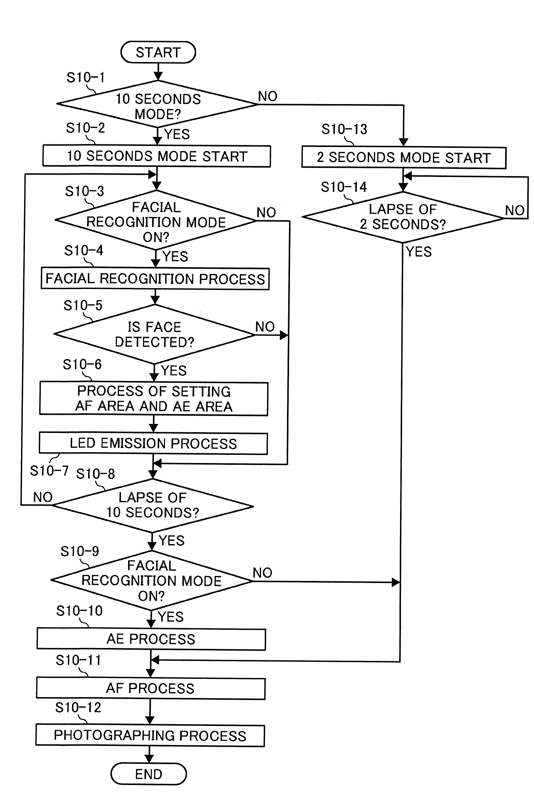
[0072]As described above, the digital camera does not need to estimate a focus position at the time of photographing, operate a pre-focus process (a distance surveying process which occurs by pressing release button halfway on commonly-used cameras), or start the self-timer mode when pressing the release halfway. In sum, the digital camera avoids troublesome operations and the digital camera starts the self-timer mode facing a suitable direction. The digital camera obtains a photographing result, which focuses a subject face and has a suitable exposure even when the photographer is a subject person and the digital camera reoperates the photographing process quickly because the digital camera detects a face area of a subject person, and operates the AF process and AE process based on the face area for 10 seconds (2 seconds) after the self-timer mode starts. The present invention including this and other embodiments allows a good and quick result using facial detection when the photo...
third embodiment
[0077]As described above, the digital camera does not need to estimate a focus position at the time of photographing, operate a pre-focus process (a distance surveying process which occurs by pressing release button halfway on commonly-used cameras), or start the self-timer mode when pressing the release halfway. In sum, the digital camera avoids troublesome operations and the digital camera starts the self-timer mode facing a suitable direction. The digital camera obtains a photographing result, which focuses a subject face and has a suitable exposure even when the photographer is a subject person and the digital camera reoperates the photographing process quickly because the digital camera detects a face area of a subject person, and operates the AF process and AE process based on the face area for 10 seconds (2 seconds) after the self-timer mode starts. The present invention including this and other embodiments allows a good and quick result using facial detection when the photo...
PUM
 Abstract
Description
Claims
Application Information