Light source unit for use in a backlight module

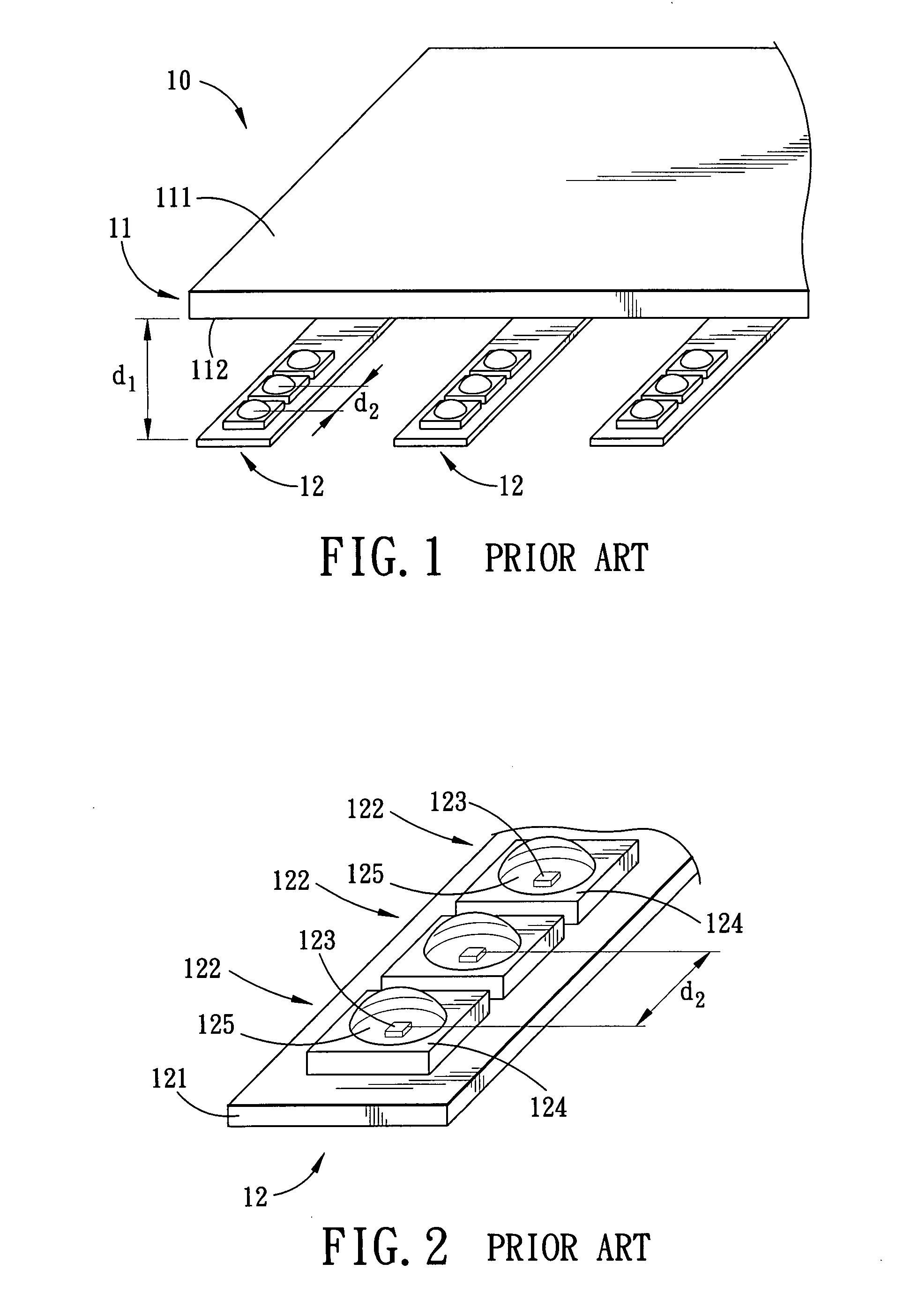
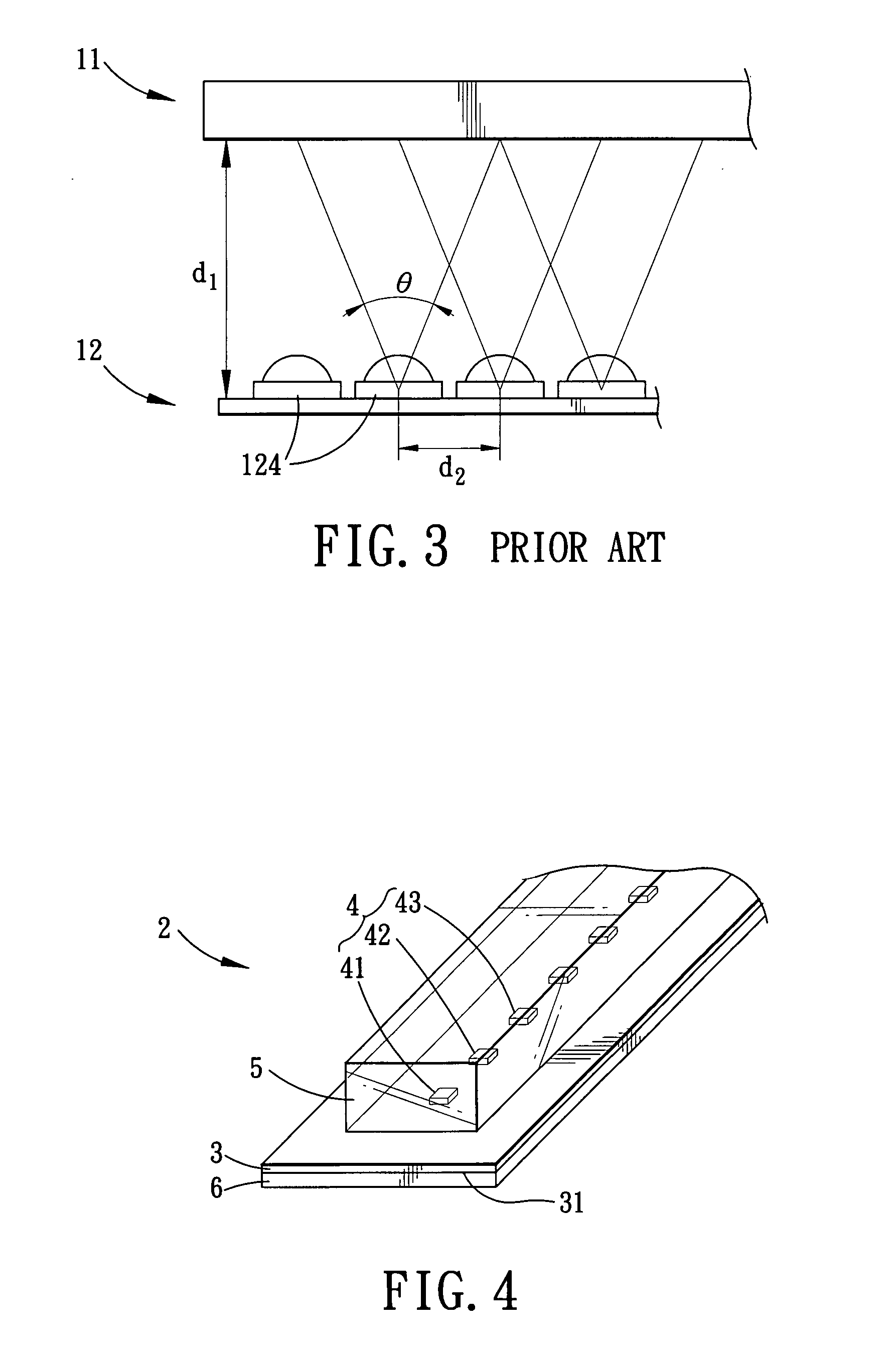
a backlight module and light source technology, applied in the direction of planar/plate-like light guides, lighting and heating apparatus, instruments, etc., can solve the problem of inability to reduce the light mixing distance (db>1/b>), the shortening of the light mixing distance between the light entering side b>112/b> of the light guide plate, and the inability to further shorten the chip spacing or distance (db>2/b>) may

Inactive Publication Date: 2008-05-29
LITE ON TECH CORP
View PDF10 Cites 45 Cited by
  • Summary
  • Abstract
  • Description
  • Claims
  • Application Information

AI Technical Summary

Benefits of technology

[0027]Since the light source unit of this invention has the advantage of shortening the light mixing distance, when applied to the side light type backlight module, a di

Problems solved by technology

Further shortening of the chip spacing or distance (d2) may not be feasible due to the fixed size of the package base 124.
As a result, the light mixing distance (d1) ca

Method used


Image

  • Light source unit for use in a backlight module
  • Light source unit for use in a backlight module
  • Light source unit for use in a backlight module

Examples


Embodiment Construction

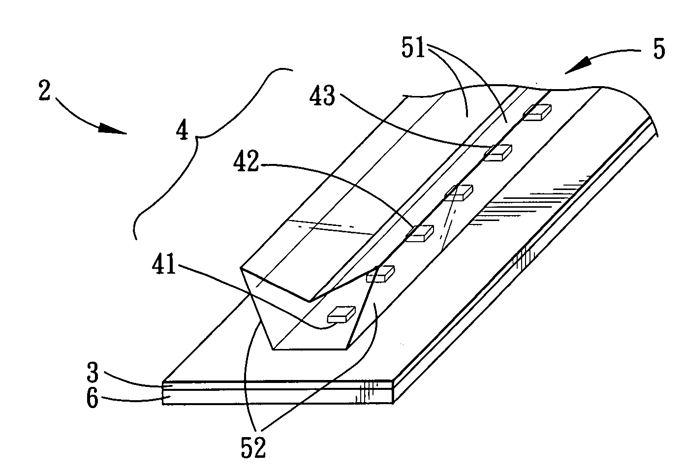
[0043]With reference to FIG. 4, the preferred embodiment of a light source unit 2 according to the present invention is adapted for use in a backlight module, and includes a circuit substrate board 3, a plurality of LED chip assemblies 4 provided on the circuit substrate board 3, an encapsulating member 5 for encapsulating the chip assemblies 4, and a heat dissipating member 6 disposed on a bottom face 31 of the circuit substrate board 3.

[0044]The circuit substrate board 3 is an elongated strip of printed circuit board (PCB), and is formed with a circuit pattern using micro-lithography. Aside from using a rigid printed circuit board, a flexible circuit board or a composite circuit board can also be used for the circuit board substrate 3.

[0045]The chip assemblies 4 are arranged along a first direction of the circuit substrate board 3. In this embodiment, the chip assemblies 4 are arranged linearly and directly on a top face of the circuit substrate board 3 along a long-axis direction...


PUM


Abstract

A light source unit for use in a backlight module includes a circuit substrate board and a plurality of chip assemblies arranged along a first direction of the circuit substrate board. Each of the chip assemblies includes a red LED chip, a blue LED chip, and a green LED chip. By employing a chip on board (COB) concept, and by providing LED chips of three primary colors directly on the circuit substrate board, chip spacing can be considerably reduced to effectively shorten the light mixing distance so as to permit miniaturization of the backlight module incorporating the light source unit.

Description

CROSS-REFERENCE TO RELATED APPLICATION[0001]This application claims priority of Taiwanese Application No. 095143374, filed on Nov. 23, 2006.BACKGROUND OF THE INVENTION[0002]1. Field of the Invention[0003]The invention relates to a light source unit for use in a backlight module, more particularly to a light source unit capable of shortening a light mixing distance to permit miniaturization of a backlight module incorporating the same.[0004]2. Description of the Related Art[0005]With the continuous trend toward miniaturization of liquid crystal display modules, backlight modules that provide planar light sources for liquid crystal display modules need to be improved in order to conform to the current trend.[0006]Due to color rendering performance and environmental concerns, conventional backlight modules that employ cold cathode fluorescent lamps (CCFL) have been gradually replaced by light emitting diodes (LED) that have better color rendering properties and that do not contain merc...

Claims


Application Information

Patent Timeline
IPC IPC(8): F21V8/00
CPCG02B6/0025G02F1/133603G02B6/0068G02B6/003G02B19/0066G02B19/0028
Inventor PAN, CHANG-HUNGHUANG, CHEN-HUA
Owner LITE ON TECH CORP
Why Eureka
Try Eureka