Eureka AIR delivers breakthrough ideas for toughest innovation challenges, trusted by R&D personnel around the world.

Apparatus and method for switching an apparatus to a power saving mode

Inactive Publication Date: 2008-05-29
POLARIS INNOVATIONS
View PDF11 Cites 27 Cited by
  • Summary
  • Abstract
  • Description
  • Claims
  • Application Information

AI Technical Summary

Benefits of technology

[0007]An embodiment of an apparatus being connectable, as a latch stage into an asynchronous latch chain comprises a reception interface, wherein upon receipt of a first signal at the reception interface the apparatus switches to one of the first power saving mode and a second power saving mode, depending on the second signal at the reception interface, wherein the apparatus offers a first power consumption and a first wake-up time in the first power saving mode and a second power consumption and a second wake-up time in the second power saving mode, wherein the first power consumption is higher than the second power consumption and wherein the first wake-up time is shorter than the second wake-up time.
[0008]According to a further embodiment of the present invention, a memory system comprises a memory controller, a plurality of memory modules coupled to the memory controller in an asynchronous latch chain configuration, the pluralit

Problems solved by technology

However, in modern computer systems, a key issue is the power management and power consumption.
For instance, in the field of mobile computing, the available power is limited by the accumulators and / or the batteries available.
Moreover, in the field of stationary computers, power consumption is a great issue, as the power dissipated has to be transported away from the components preventing overheating of the respective circuitries and components.
In other words, measures taken to reduce the power consumption exhibits a strong negative influence on the performance of the computer system, especially the computing power and the available and effective bandwidth of bus structures, which are required for the transport of data between different components of the computer system, for instance, between a processor and the memory.
In this context analog circuits used in interfaces exhibit, for example, a large power saving potential but suffer from the fact that they need a long time to recover again since, for instance, control loops and other feedback loops are needed to reach and maintain a stable working point and a stable working condition, before these interfaces can provide a reliable and fast data communication between the components attached.

Method used


Image

  • Apparatus and method for switching an apparatus to a power saving mode
  • Apparatus and method for switching an apparatus to a power saving mode
  • Apparatus and method for switching an apparatus to a power saving mode

Examples


Embodiment Construction

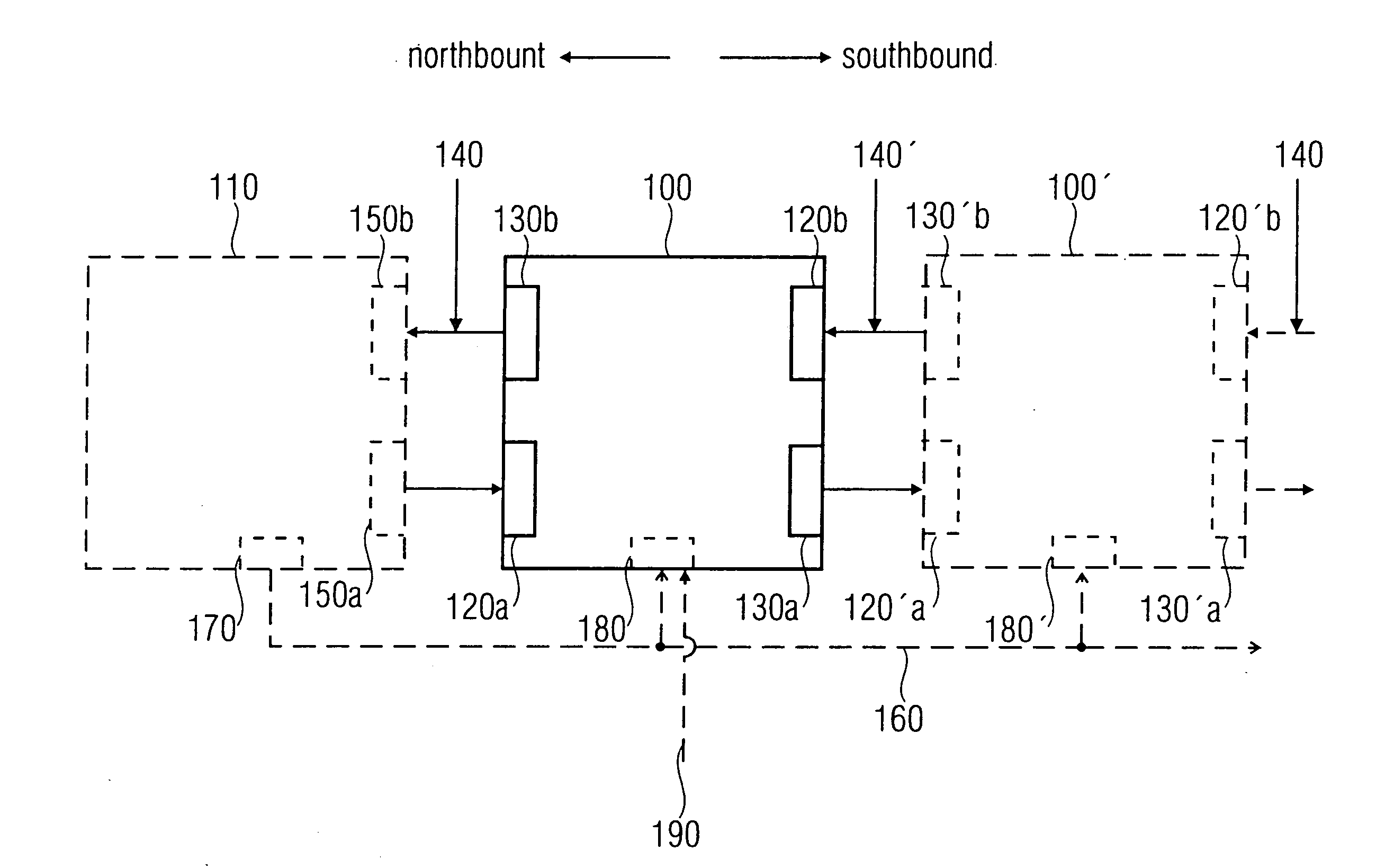
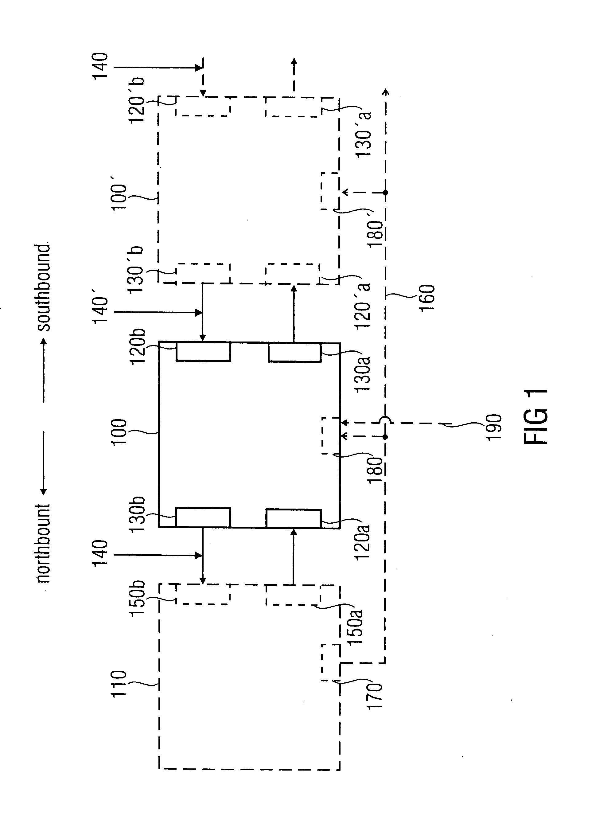
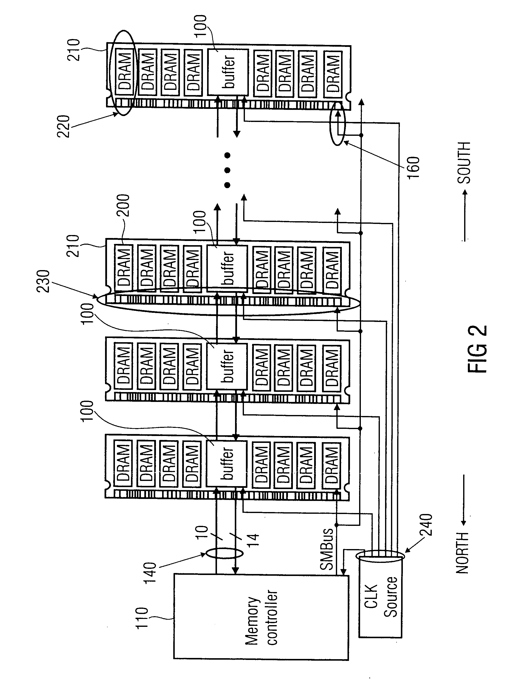
[0012]FIGS. 1 and 2 show block diagrams of an embodiment of an apparatus being connectable as a latch stage into an asynchronous latch chain and an embodiment of a memory system. Before a second embodiment of the present invention is described with respect to FIG. 2, a first embodiment of an apparatus being connectable as a latch stage into an asynchronous latch chain is explained with respect to the schematic representation of an embodiment of the apparatus and an embodiment of a memory system shown in FIG. 1.

[0013]FIG. 1 shows an embodiment of an apparatus 100 integrated into an embodiment of a memory system according to the present invention. The memory system comprises, apart from the apparatus 100 shown in the center of FIG. 1, a further apparatus 100′ and a memory controller 110 forming an asynchronous latch chain or a daisy chain as will be explained below.

[0014]In a so-called daisy chain configuration, components of the daisy chain, which are also referred to as latch stages...


PUM


Abstract

An apparatus being connectable as a latch stage into a asynchronous latch chain comprises a reception interface, wherein upon receipt of the first signal at the reception interface, the apparatus switches to one of the first power saving mode and a second power saving mode, depending on the second signal at the reception interface and wherein the apparatus offers a first power consumption and a first wake-up time in the first power saving mode, and a second power consumption and a second wake-up time in the second power saving mode.

Description

TECHNICAL FIELD[0001]The present invention relates to an apparatus and method for switching an apparatus to a power saving mode, for instance to an apparatus being connectable, as a latch stage into an asynchronous latch chain, for instance, a memory buffer for a memory bus in a memory system.BACKGROUND[0002]Modern computer systems offer a significant amount of computing power, as well as a large memory capacity, which enables fast and highly complex computations, as well as fast handling and processing of data. However, in modern computer systems, a key issue is the power management and power consumption. For instance, in the field of mobile computing, the available power is limited by the accumulators and / or the batteries available. Moreover, in the field of stationary computers, power consumption is a great issue, as the power dissipated has to be transported away from the components preventing overheating of the respective circuitries and components.[0003]Many computer systems a...

Claims


Application Information

Patent Timeline
IPC IPC(8): G06F1/32
CPCG06F1/3203G06F1/3225G06F1/3275G06F13/1673Y02B60/1228G11C5/148Y02B60/1225Y02B60/32G11C5/04Y02D10/00Y02D30/50G06F1/32G06F12/00
Inventor PRETE, EDOARDOTROST, HANS-PETERSANDERS, ANTHONYSCHEIDELER, DIRKBRAUN, GEORGWOOD, STEVELUYKEN, RICHARD JOHANNES
Owner POLARIS INNOVATIONS
Why Eureka
Eureka Blog
Learn More