Step-adjustable tire pressure monitoring sensor signal housing assembly

a technology of tire pressure monitoring and signal housing, which is applied in vehicle tyre testing, instruments, roads, etc., can solve the problems of unsecured and loose installation, difficult installation, and difficult heat dissipation

Active Publication Date: 2008-06-05
BAOLONG HUF SHANGHAI ELECTRONICS CO LTD
View PDF8 Cites 20 Cited by
  • Summary
  • Abstract
  • Description
  • Claims
  • Application Information

AI Technical Summary

Benefits of technology

[0005]The advantage is that the connecting face of the said sensor signal housing and the cylinder of the D block are concentric arcs.
[0006]The advantage is that the said Slot 1 is a curve long slot, the said Slot 3 and ratchet teeth are in a same direction.
[0007]The advantage is that said assembly further includes two rubber columns and on both sides of the signal housing each has a connecting hole, the said rubber columns fix the signal housing onto the rim through the connecting holes.
[0008]The advantage is that the number of ratchet teeth is 1˜7.

Problems solved by technology

However, a tire valve has to be installed externally due to the special closed structure of tires, and a prior tire valve with an installed electronic signal housing (containing monitoring elements and batteries) is much larger than a traditional one, so it is difficult to install.
However, if the signal housing on the tire valve is completely connected to the rim, the friction heat generated by the high speed rotating rim will be transferred to the electronic signal housing in the tire and influence the reliability of the electronic elements (heat dissipation is difficult).
In addition, the centrifugal caused by the high speed rotating tire changes with the change of speed and road evenness, so the radial load applied on the tire valve changes unceasingly resulting in unsecured and loose installation.
In addition, the rims are circular and their radius, arc size and shape differ from one another, so the electronic signal housing on the tire valve may not be connected properly to the rim, and one size of electronic signal housing cannot apply to multiple sizes of rims.
Therefore, there are few of products which can reliably, successfully and economically used for commercial purposes in China and abroad.
The main reason is that the design structure is complicated and lack of commercial practicability.
For example, for some products in which the electronic signal housing fixed on the rim by a steel strip, the steel strip is liable to loosing and falling off with vibration; for some products with the electronic signal housing is bonded on the rim with glue, the electronic elements may be overheated and damaged because the humidity and temperature conditions are severe and the housing is connected to the rim (steel or aluminum), the heat generated by braking will be transferred to the housing to cause the electronic elements inside overheated, in addition, the adhesion of the glue will deteriorate after a long period of operation resulting in falling of, and for some products in which the tire valve is molded with the electronic signal housing, the housing and the tire valve cannot be rotated and adjusted, and with a same process precision, one size of signal housings is only applicable for 1 size of rims.
There are also some products with adjustable electronic signal housing and tire valve, but it is hard to ensure the stability of the structure, and a long period of vibration will cause looseness.

Method used


Image

  • Step-adjustable tire pressure monitoring sensor signal housing assembly
  • Step-adjustable tire pressure monitoring sensor signal housing assembly
  • Step-adjustable tire pressure monitoring sensor signal housing assembly

Examples


Embodiment Construction

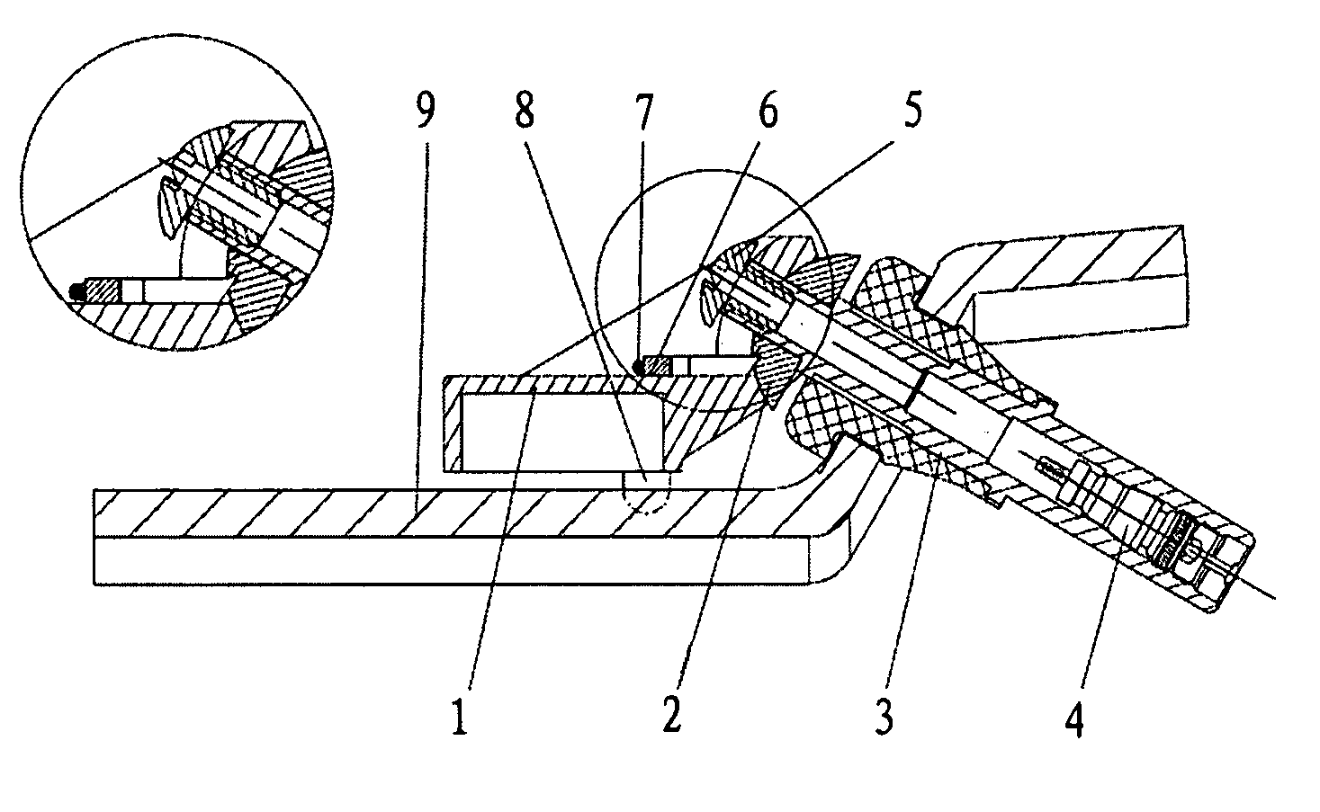
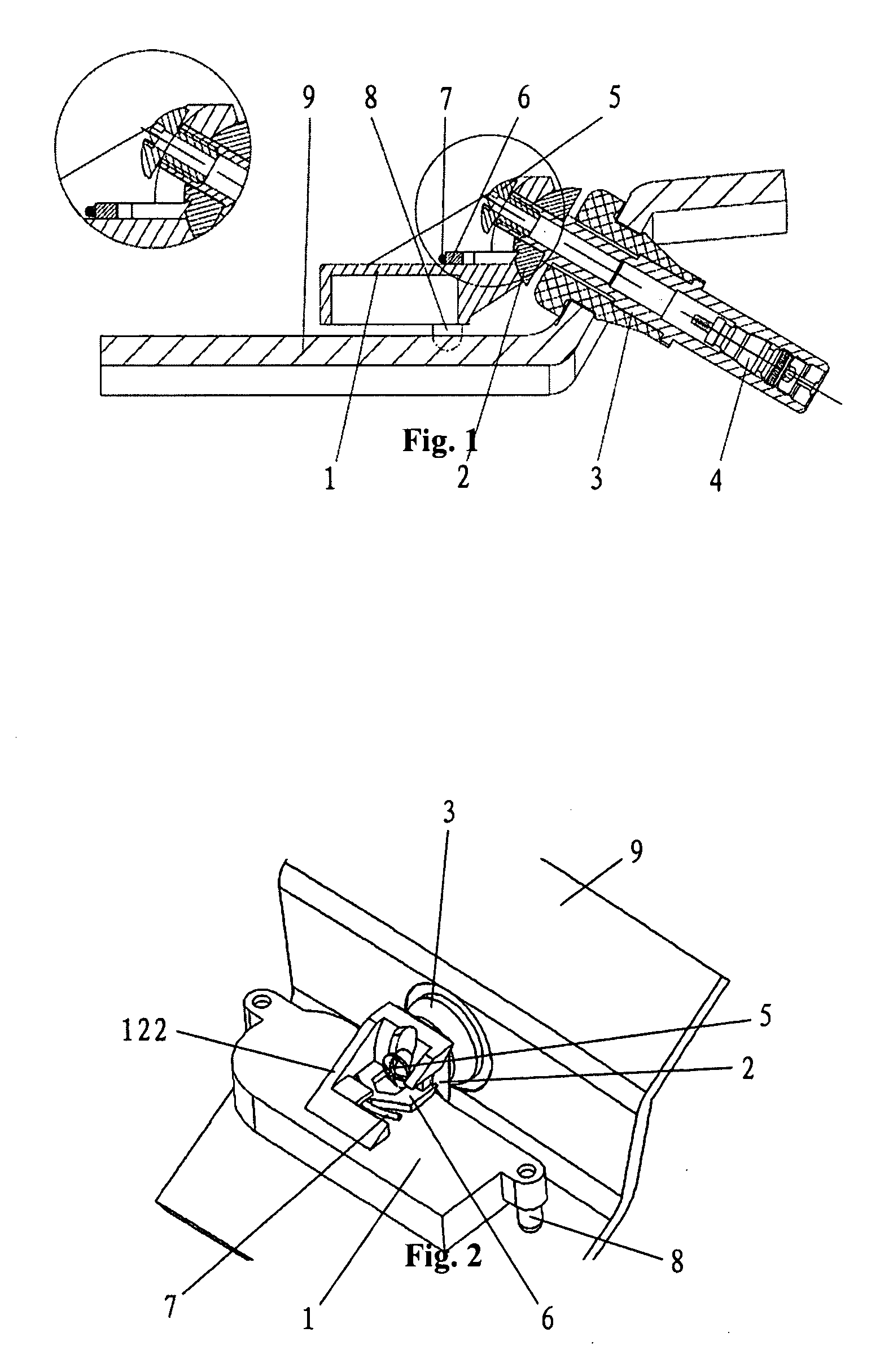
[0015]The tire pressure monitoring sensor signal housing assembly of this present invention is shown in FIG. 1, consisting of sensor signal housing 1, a D block 2, a valve 3, a valve inside 4, a screw 5, a U-pawl 6, a spring 7 and a rubber column 8.

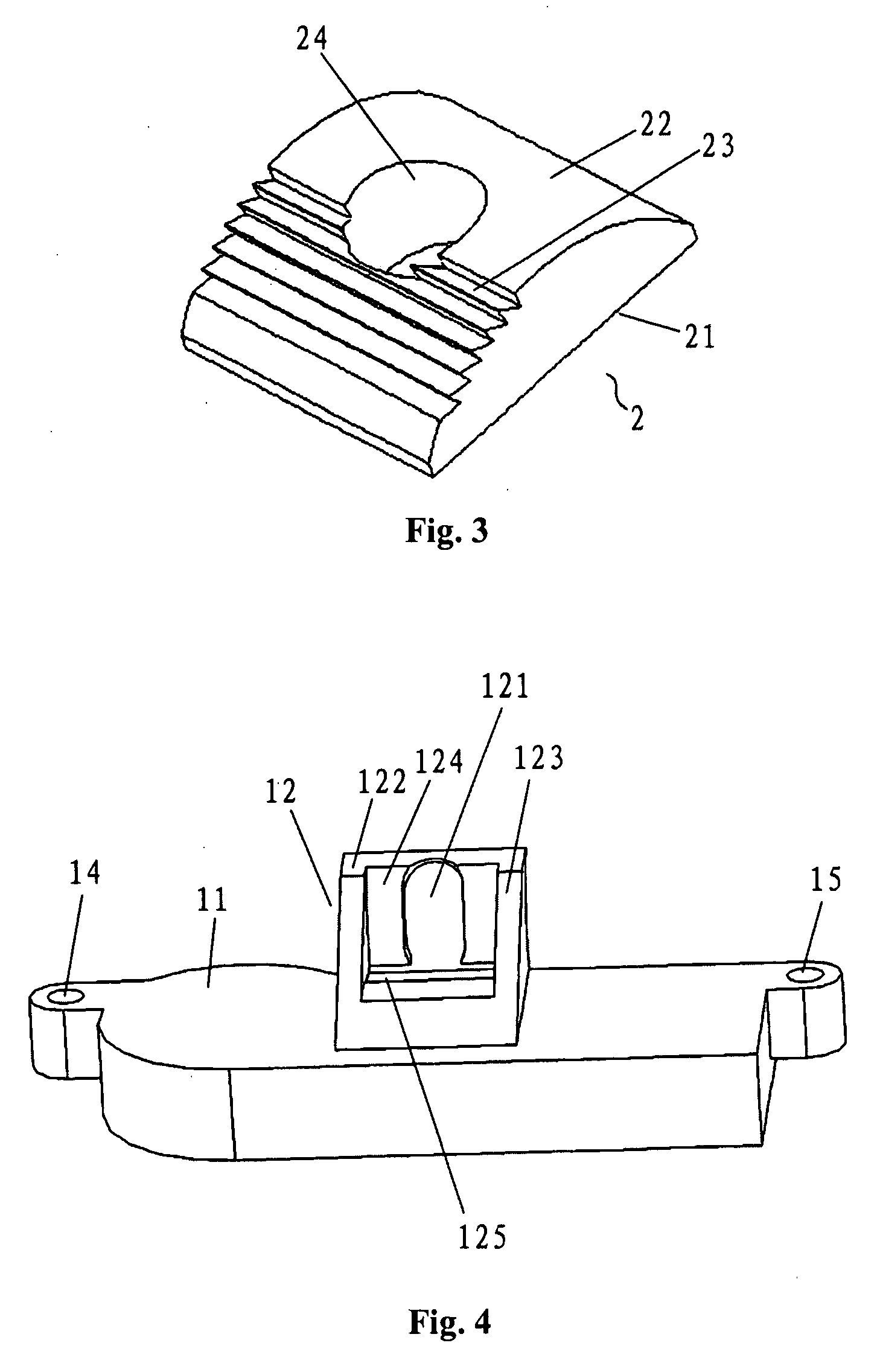
[0016]The sensor signal housing 1 is shown in FIG. 4, including a housing holder 11 and a connecting part 12 on the center of housing holder 11. The connecting part 12 consists of two symmetrical connectors 122 and 123 and a curving connecting face 124 between the connector 122 and 123, a long slot 121 is provided perpendicular to the connecting face 124. A pawl sliding slot 12 is horizontally provided under the connector 122 and 123. Besides, two symmetrical connecting holes 14 and 15 are also provided on both sides of signal housing 11.

[0017]The structure of the D block 2 is shown in FIG. 3 which is in D shape, including a flat part 21 and a cylinder part 22. A mounting hole 24, which is perpendicular to the flat part 21, is provided on...


PUM


Abstract

This present invention discloses a step-adjustable tire pressure monitoring sensor signal housing assembly including a valve and a valve core fixed on a rim, a sensor signal housing which consists of a housing holder and a connecting part, the connecting part has a curve connecting face where a Slot 1 is provided, and a Slot 3 is provided on the housing holder under the connecting part; a D block, which is in D shape and has a flat part and a cylinder part, a Slot 2 is provided in the center of the cylinder part perpendicular to the flat part, some ratchet teeth are provided longitudinally in the cylinder part by the side of a mounting hole; a U-pawl and a spring, which are installed in the Slot 3, the spring is in the bottom of the U-pawl and the top of the U-pawl is corresponding to the ratchet teeth on the D block; and a connector which fixes the sensor signal housing and the D block onto the tire valve through the Slot 1 in the signal housing and the Slot 2 on the D block. This present invention is applicable for all the rims of 5˜35°, and therefore is widely applicable and easy to install.

Description

FIELD OF THE INVENTION[0001]This present invention involves a ratchet signal housing assembly containing an automobile tire pressure monitoring sensor (TPMS), the rotating angle of which can be adjusted to apply for the rims of 5°˜35°.PRIOR ART[0002]Inflation is required for all vehicle tires at present. As the tire pressure concerns the driving safety of vehicles, it is necessary to install electronic safety sensors on tires for real time monitoring of the tire pressure. Vehicle manufacturers in different countries have launched out monitoring devices consisting of an electronic sensor and a tire valve for installing on vehicle tires to monitor the tire pressure. However, a tire valve has to be installed externally due to the special closed structure of tires, and a prior tire valve with an installed electronic signal housing (containing monitoring elements and batteries) is much larger than a traditional one, so it is difficult to install. In addition, there are various sizes of v...

Claims


Application Information

Patent Timeline
Patent Type & Authority Applications(United States)
IPC IPC(8): B60C23/02
CPCB60C23/0494Y10T137/36B60C23/04B60C23/0442B60C29/02
Inventor QIU, ZHENFANGHUANG, JIANSONGCHEN, ZHIDONG
Owner BAOLONG HUF SHANGHAI ELECTRONICS CO LTD
Why Eureka
Try Eureka