Rennet injection apparatus and method

a technology of rennet and injection apparatus, which is applied in the field of cheese process vat, can solve the problems of uneven wear, unbalanced weight distribution of agitator panels, and uneven rotation of agitator shafts, and achieve uniform or even wear on parts, eliminate agitator shaft distortion, and minimize the effect of lost production tim

Inactive Publication Date: 2008-06-05
ADVANCED PROCESS TECH
View PDF25 Cites 8 Cited by
  • Summary
  • Abstract
  • Description
  • Claims
  • Application Information

AI Technical Summary

Benefits of technology

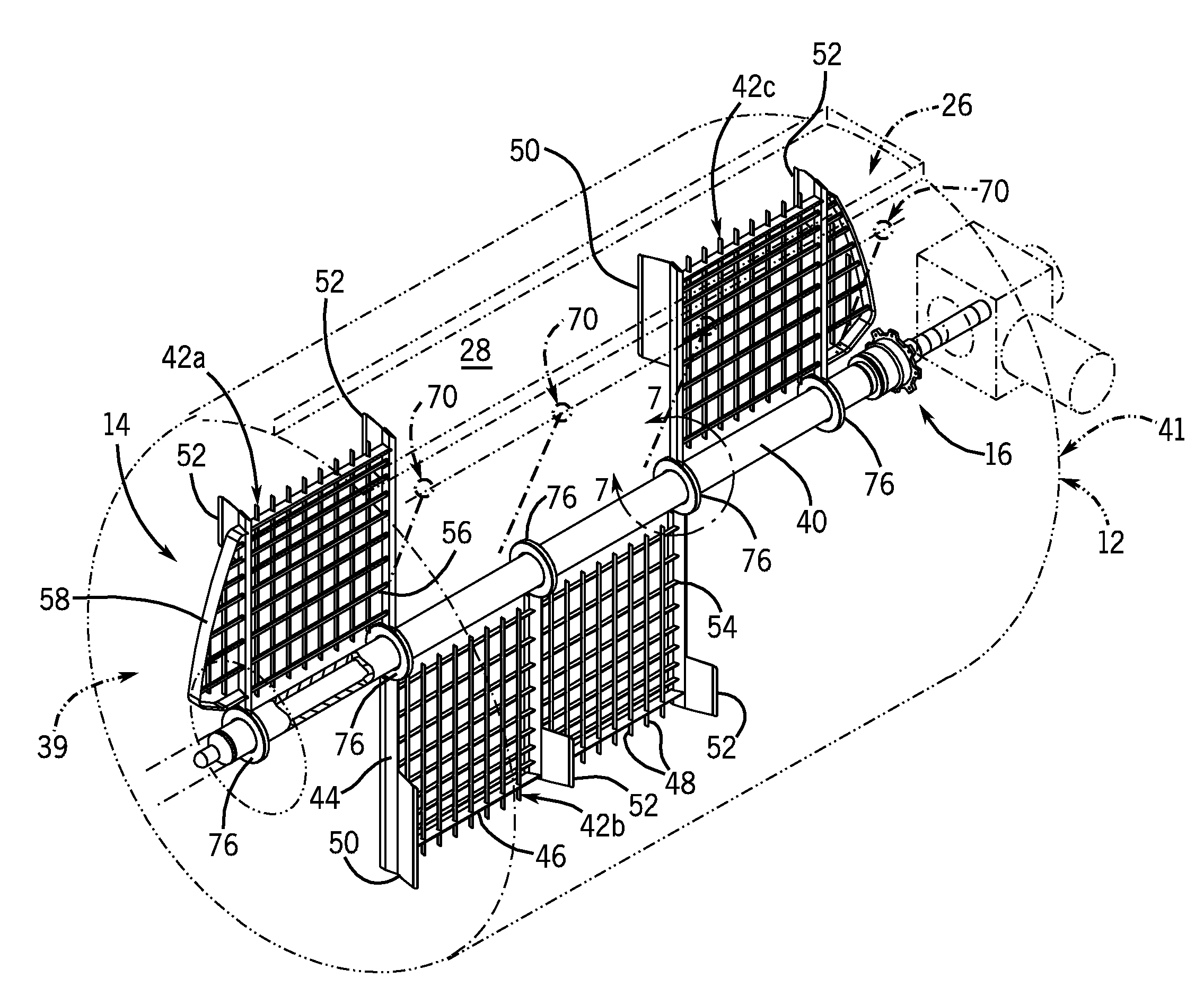
[0030]The present invention further includes a unique arrangement of the agitator panels. In preferred embodiments, the agitator panels are substantially balanced along an axis of the agitator shaft in a generally planar fashion. Substantially balanced agitator panels provide uniform or even wear on parts, like motor parts, speed reducer parts, variable frequency drive parts and the like. This wear reduction minimizes lost production time and product loss due to mid-cycle vat break-downs caused by premature failure of the previously mentioned parts.
[0031]The agitator shaft assembly of the present invention preferably further includes disk-like collars that are welded to the agitator shaft while the agitator shaft is external to the vat body. If necessary, the agitator shaft can be straightened at that time with known methods and techniques. After installation of the straightened agitator shaft, the agitator panels are welded to the outer diameter of the disk-like collars. Welding to the outer diameter of the disk-like collars virtually eliminates any agitator shaft distortion caused by heat generated during the welding process. In addition, the disk-like collar is believed to be gentler on the coagulum when the agitator shaft rotates because the number of blunt edges being forced through the coagulum is minimized.
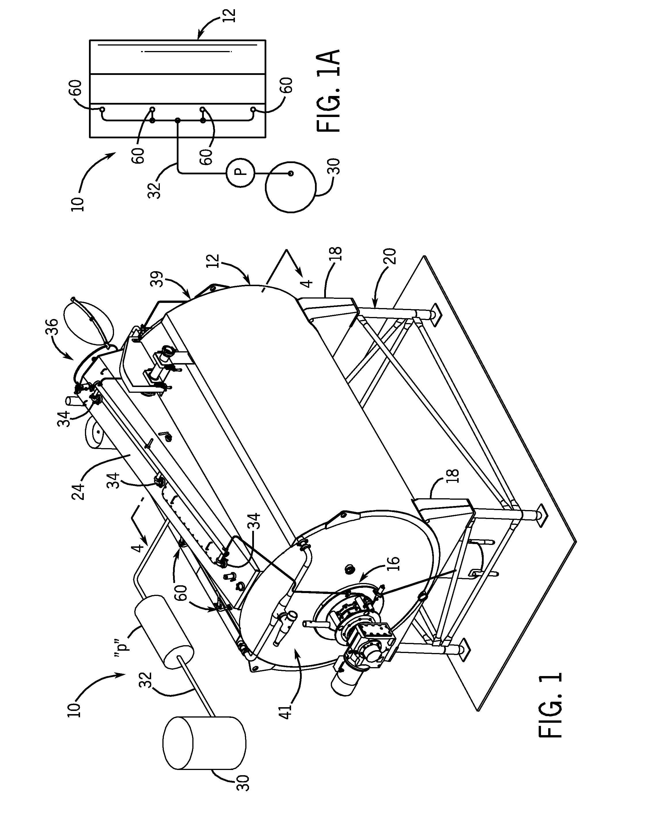
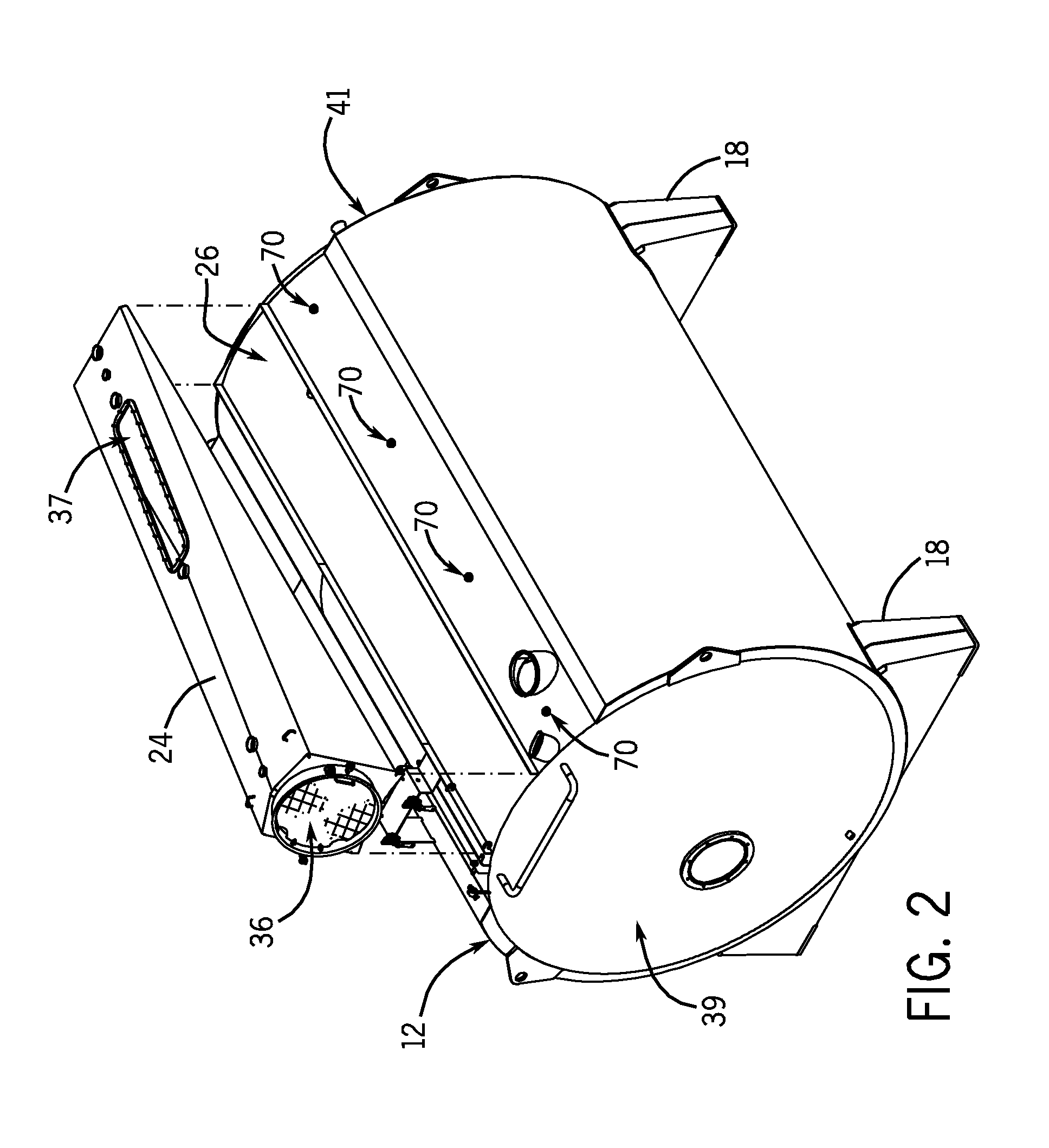
[0033]Additionally, the cheese process vat of a further embodiment of the present invention further includes an injection nozzle assembly, even more preferably, a plurality of injection nozzle assemblies. Each injection nozzle assembly can inject a stream of a rennet solution through the surface of the fluid milk within the vat body well below the surface of the fluid milk, thereby providing a more effective distribution of the rennet solution. This process of injecting the rennet mixture below the surface of the fluid milk improves the cheese making process by incorporating the aqueous rennet solution into the milk faster, more pervasively and more effectively. An effective incorporation of the rennet solution will create coagulation that is substantially uniform throughout the fluid milk thereby increasing yield.
[0036]In preferred embodiments of the present cheese process vat the face seal may be adjusted without having to enter the vat body and without having to take the seal assembly apart and rebuild it. To adjust the face seal, the user simply loosens the external fasteners holding the seal assembly together and removes at least one shim from each fastener, then retightens the respective fasteners. The shims provide an easy way to adjust or increase lip pressure against the inner face of inner face wear plate.
[0037]Thus, it is an object of the present invention to provide a cheese process vat having a horizontal agitator shaft having substantially balanced agitator panels in both surface area and weight.
[0039]Thus, it is yet another object of the present invention to provide a cheese process vat having an easily adjustable shaft seal assembly that includes a fluid accessible cleaning chamber.

Problems solved by technology

Previous cheese process vats having single horizontal agitator shafts typically have a majority of their blade clusters or agitator panels on one side of the agitator shaft with blade panels generally confined to about 100° or less of the full 360° radius of the agitator shaft, creating a substantially unbalanced weight distribution with respect to the placement of the agitator panels within the agitator shaft assembly.
To compensate for this rolling / rotating action, it is usually necessary to increase the speed of the agitator shaft assembly, which is believed to negatively influence yield, by shattering the coagulum, thus allowing fat release and creation of cheese fines that are drained out of the curd with the whey when the whey is separated from the cheese curds.
Further, if a horizontal agitator shaft assembly has a substantially unbalanced weight distribution with respect to the placement of the agitator panels along the agitator shaft, the motor, speed reducer and bearings experience uneven loads as the agitator shaft rotates.
This can cause uneven wear and premature failure of the above mentioned parts.
The blunt edges of the stubs during the cutting phase can damage the coagulum enough to negatively affect product yield.
This can be counter productive, however, as the coagulum may not set as well under such conditions.

Method used


Image

  • Rennet injection apparatus and method
  • Rennet injection apparatus and method
  • Rennet injection apparatus and method

Examples


example 1

Performance Testing

[0097]Testing whey from cheese making operations for remaining fat content in the whey is one of the most common tests used to compare cheese making efficiently, in different vats in cheese plants throughout the industry. The results are often used as a measure of performance. By testing the amount of fat in the whey, cheese plants can predict the performance of the cheese process vats. It is desirable to have as low a fat content in the whey as possible for each type of cheese.

[0098]Performance test results for whey from a single agitator shaft vat of the present invention were compared with test results for a well known dual agitator shaft vat.

[0099]The test procedure begins by collecting a small whey sample from the cheese process vat during the “predraw / settle” step. This sample of approximately 4 to 6 ounces is sent to a commercial laboratory where the sample is tested with a standard infrared spectroscopy test for fat quantity as a percentage fluid volume. T...


PUM


Abstract

A cheese process vat is disclosed. The cheese process vat includes an enclosure and a shaft assembly, preferably a shaft assembly having a shaft and a plurality of agitator panels arranged on the shaft. The preferred cheese process vat includes a plurality of rennet solution injection assemblies to inject rennet solution into the contents of the vat such that the rennet solution sufficiently pierces the surface of the fluid contents of the vat so that the rennet solution is mixed and distributed more efficiently.

Description

BACKGROUND OF THE DISCLOSURE[0001]1. Field of the Invention[0002]The present invention relates to a cheese process vat. More specifically, the present invention relates a cheese process vat including apparatus for injecting rennet into fluid milk in the vat, below the surface of the fluid milk, as well as methods for making cheese in the same.[0003]2. Description of the Related Art[0004]In the 1970's, a number of companies manufactured enclosed vertically agitator shafted vats for making cheese and cheese-like products. These enclosed vats improved upon inconsistent cheese making results generally noted in the open cheese making vats that were common in those days. The enclosed vats also reduced the risk of foreign material contamination and the interior could be automatically cleaned with automatic, clean-in-place (CIP) spray systems. Initially, these vats had vertical agitator shafts. Such vats include the Damrow® Double O™ Vat and the Stoelting® Vertical Vat.[0005]In the late 198...

Claims


Application Information

Patent Timeline
Patent Type & Authority Applications(United States)
IPC IPC(8): A01J11/00A23C9/12A01J99/00A01J25/00
CPCA01J25/04A23C19/02A01J25/06
Inventor BOKELMANN, PAUL R.CAMPBELL, CRAIG J.STARKSON, GARY L.
Owner ADVANCED PROCESS TECH
Why Eureka
Try Eureka