
Method and device for generating mechanical energy

Inactive Publication Date: 2008-06-05
GIECHAU LUTZ
View PDF5 Cites 7 Cited by
  • Summary
  • Abstract
  • Description
  • Claims
  • Application Information

AI Technical Summary

Benefits of technology

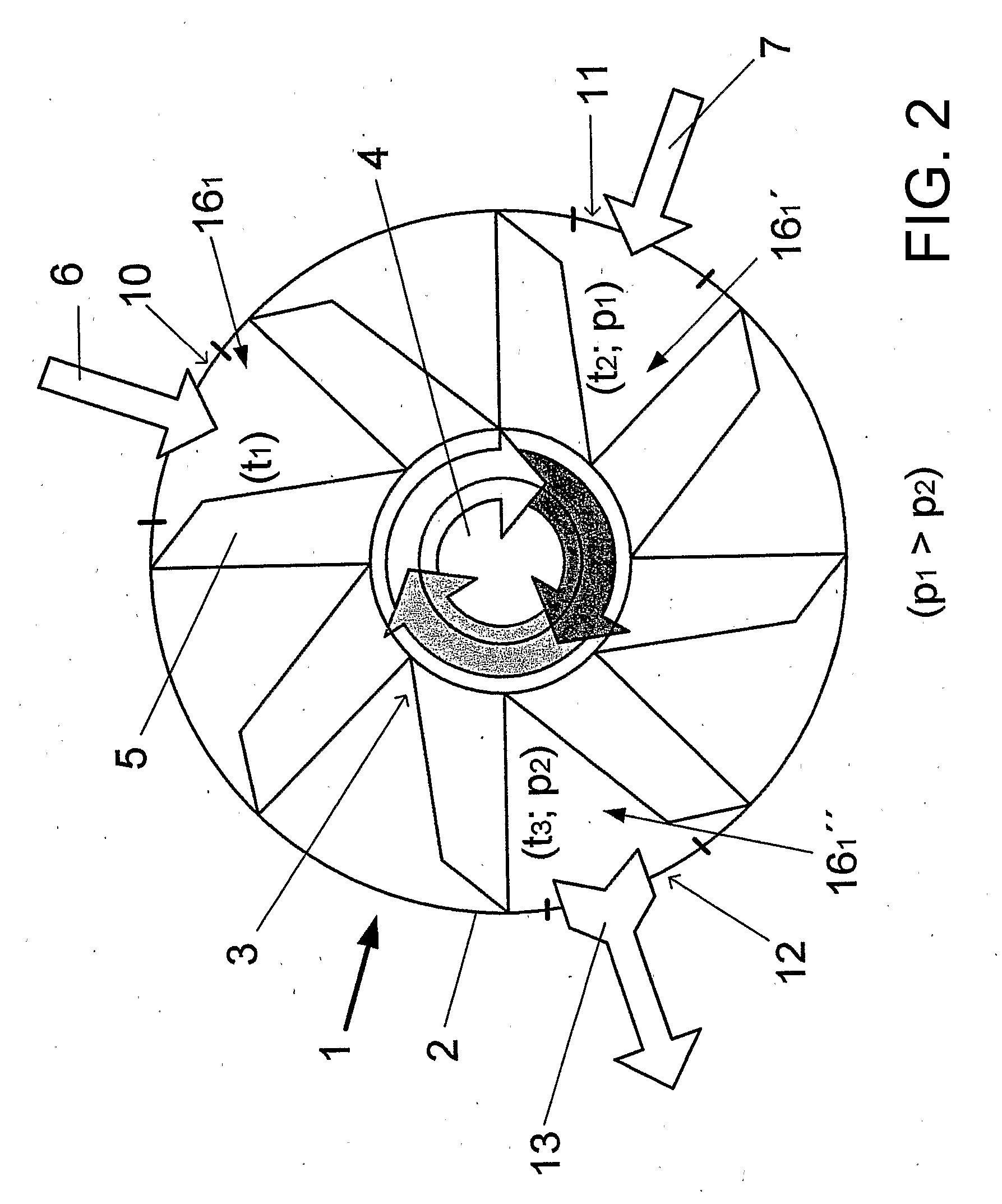
[0048]According to another feature of the invention, the at least two substantially identically formed rotating parts define a central axis and are disposed with an angular offset with respect to one another about the central axis such that an unbalance in a rotating system resulting from an expansion of a mixture of the working media is avoided.
[0066]Likewise, at least one opening for additionally charging the respective working chamber, which has already been filled with the two working media, with the at least one further working medium can be provided in the housing part, as a result of which an increase, or a further increase, in the level of efficiency of the device or of the thermal engine thereof can also be brought about.
[0068]The rotating parts can be disposed with an angular offset with respect to one another about the central axis in such a way that an unbalance in the rotating system which is formed through expansion of the working media mixture is avoided.

Problems solved by technology

The relatively high energy costs for ensuring the process prove to be one of a number of disadvantages.
Here too, considerable quantities of energy are necessary to maintain the circulation process.

Method used


Image

  • Method and device for generating mechanical energy
  • Method and device for generating mechanical energy
  • Method and device for generating mechanical energy

Examples


Embodiment Construction

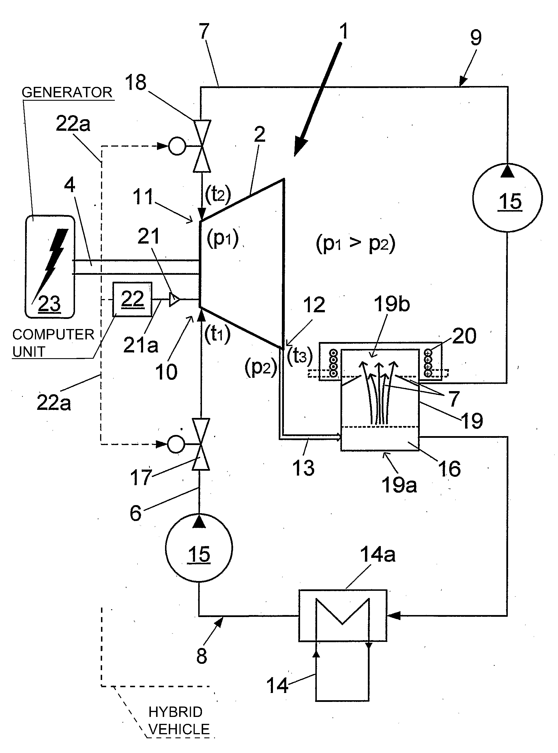
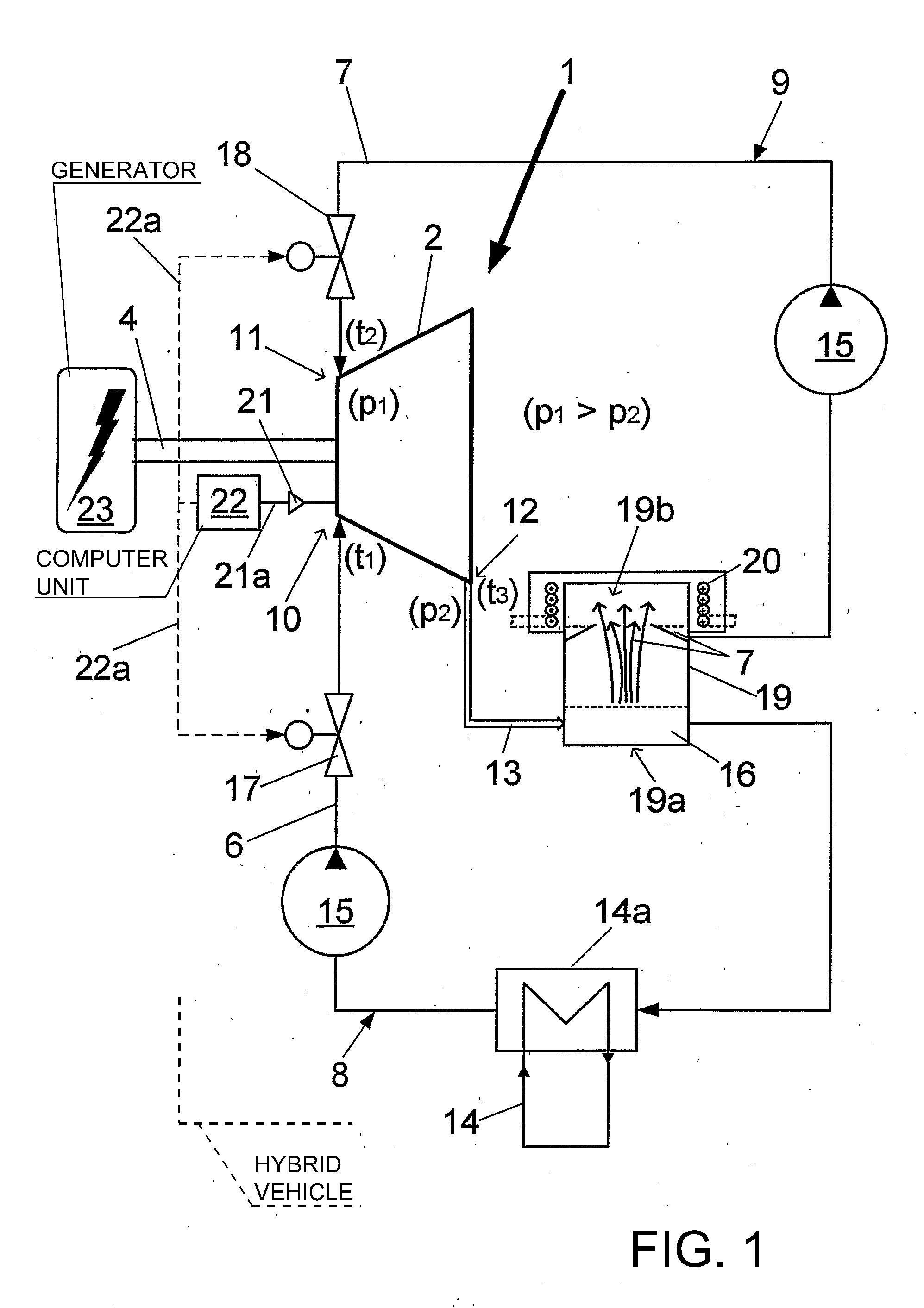
[0097]Referring now to the figures of the drawings and first, particularly, to FIGS. 1 and 2 thereof, there is shown a rotating thermal engine 1 having a housing part 2 and a part 3 which rotates therein and which is formed here by a plurality of rotor blades 5 which are disposed fixedly on a shaft 4. The thermal engine 1 which is shown corresponds, as it were in its basic structure, to a turbine which is known per se and has a turbine casing (turbine housing) and a turbine wheel which revolves therein.

[0098]According to the invention, the thermal engine 1 is operated with a first and at least one further working medium 6, 7. The working media 6, 7 are guided in different circuits 8, 9 and have a liquid aggregate state at the start of the respective circulation process or immediately before entry into the thermal engine 1.

[0099]The entire device, including in particular the thermal engine 1, the connected circuits 8, 9 and secondary assemblies, forms here a very largely closed syste...


PUM


Abstract

A method for producing mechanical energy with a rotating thermal engine includes using a first liquid working medium and at least one further liquid working medium. The at least one further working medium has a lower boiling temperature than the first working medium. When the at least one further liquid working medium is combined with the first working medium that is enriched with thermal energy, it changes to a gaseous state or expands and produces an overpressure and performs work in such a manner that a torque is applied to a rotating part of the rotating thermal engine. A device for producing mechanical energy is also provided.

Description

CROSS-REFERENCE TO RELATED APPLICATIONS[0001]This application is a continuation, under 35 U.S.C. § 120, of copending International Application No. PCT / DE2006 / 000884, filed May 22, 2006, which designated the United States; this application also claims the priority rights, under 35 U.S.C. § 119, of German Patent Application No. DE 10 2005 025 255.9, filed Jun. 2, 2005 and of German Patent Application No. DE 10 2006 021 928.7, filed May 11, 2006; the prior applications are herewith incorporated by reference in their entirety.FIELD OF THE INVENTION[0002]The invention relates to a method and a device for generating mechanical energy through the use of a rotating thermal engine having a housing part with at least one inlet duct and an outlet duct and at least one part which rotates in the housing part, wherein thermal energy is converted into mechanical work and wherein the working media that are used pass through a circulation process.BACKGROUND OF THE INVENTION[0003]Thermal engines or t...

Claims


Application Information

Patent Timeline
IPC IPC(8): B60K6/00F01K13/00F01K7/16
CPCF01K25/06F01K25/04
Inventor GIECHAU, LUTZ
Owner GIECHAU LUTZ
Learn More