Composite Panel with Reinforced Recesses

Inactive Publication Date: 2008-06-05
NASA
View PDF31 Cites 30 Cited by
  • Summary
  • Abstract
  • Description
  • Claims
  • Application Information

AI Technical Summary

Benefits of technology

[0007]Accordingly, it is an object of the present invention to provide a composite panel capable of low noise transmissi

Problems solved by technology

If the composite panel is to be used to define an—interior space, noise radiated by the composite panel into the inte

Method used


Image

  • Composite Panel with Reinforced Recesses
  • Composite Panel with Reinforced Recesses
  • Composite Panel with Reinforced Recesses

Examples


Example

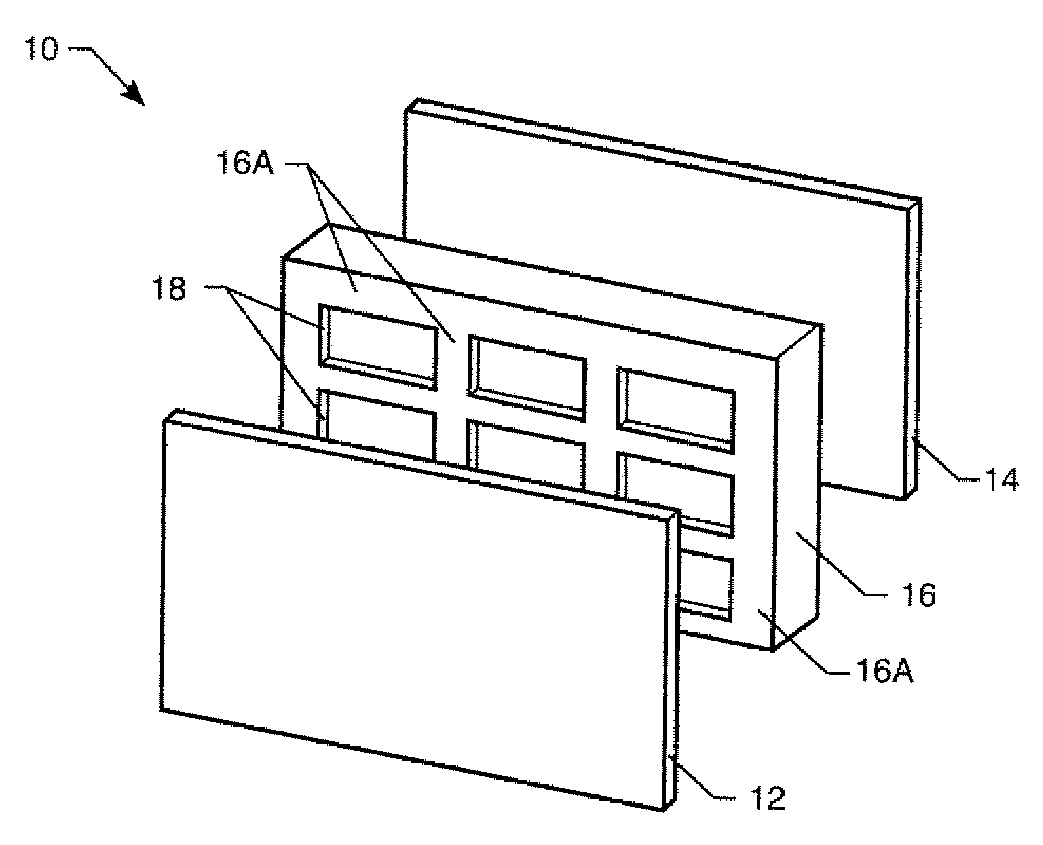
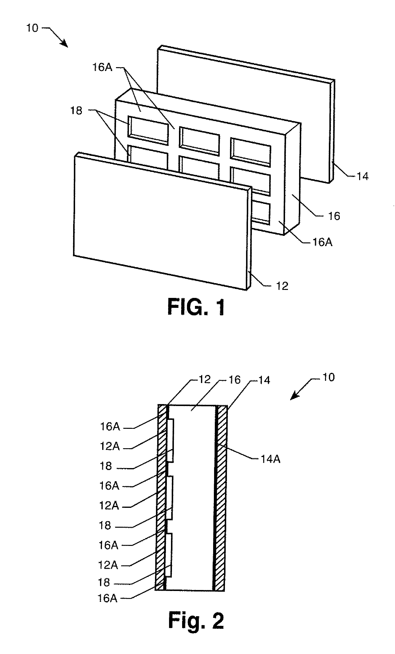
[0022]Referring now to the drawings, and more particularly to FIGS. 1 and 2, a composite panel in accordance with an embodiment of the present invention is shown and is referenced generally by numeral 10. For illustration, composite panel 10 is a flat panel. However it is to be understood that composite panels constructed in accordance with the present invention can also be shaped to define contoured panels as needed.

[0023]Composite panel 10 has face sheets 12 and 14 sandwiched about a core 16. Face sheets 12 and 14 can be the same or different materials. Suitable materials for face sheets 12 and 14 include, but are not limited to, graphite epoxy, aluminum and fiberglass. Core 16 is a lightweight material that is bonded, attached or adhered (in ways well understood in the art) to face sheets 12 and 14 to form composite panel 10 such that the stiffness of composite panel 10 is greater than the stiffness of it's component parts. As a result, while the transverse wave speed for typical...


PUM

PropertyMeasurementUnit
Sizeaaaaaaaaaa
Speedaaaaaaaaaa
Acoustic propertiesaaaaaaaaaa

Abstract

A composite panel has one or more recesses, or smoothly-contoured recesses formed in one or both opposing sides of a core. Reinforcement conforming to each recess is coupled to the core at the recess. First and second facing sheets are respectively coupled to the first and second opposing sides of the core.

Description

ORIGIN OF THE INVENTION[0001]The invention described herein was made by employees of the United States Government and may be manufactured and used by or for the Government for governmental purposes without the payment of any royalties thereon or therefor. This is a continuation-in-part of co-pending application Ser. No. 11 / 129,755, filed May 13, 2005. Pursuant to 35 U.S.C. §120, the benefit of priority from co-pending application Ser. No. 11 / 129,755, is claimed, and further pursuant to 35 U.S.C. §119, the benefit of priority from provisional application 60 / 867,466, with a filing date of Nov. 28, 2006, is claimed for this non-provisional application.CROSS-REFERENCE TO RELATED PATENT APPLICATIONS[0002]This patent application is co-pending with one related patent application entitled “COMPOSITE PANEL HAVING SUBSONIC TRANSVERSE WAVE SPEED CHARACTERISTICS”, U.S. Patent Publication No. 2006 / 0272279, owned by the same assignee as this patent application.BACKGROUND OF THE INVENTION[0003]1. ...

Claims


Application Information

Patent Timeline
IPC IPC(8): B32B3/12B32B3/00E04B1/82
CPCB32B3/12E04B1/86E04B2001/748E04B2001/8471E04B2001/8476Y10T428/24612E04C2/296E04C2/365G10K11/16Y10T428/24149E04C2/22
Inventor PALUMBO, DANIEL L.KLOS, JACOBGROSVELD, FERDINAND W.CASTLE, WILLIAM D.
Owner NASA
Why Eureka
Try Eureka