Variable inductor

Inactive Publication Date: 2008-06-05
SIRIFIC WIRELESS CORP
View PDF1 Cites 37 Cited by
  • Summary
  • Abstract
  • Description
  • Claims
  • Application Information

AI Technical Summary

Benefits of technology

[0010]It is an object of the present invention to obviate or mi

Problems solved by technology

However, many current variable inductors, such as the one shown in FIG. 1, can not be used as a continuous variable inductor since they are not connected to the primary inductor and therefore the range of inductance valu

Method used


Image

  • Variable inductor
  • Variable inductor
  • Variable inductor

Examples


Embodiment Construction

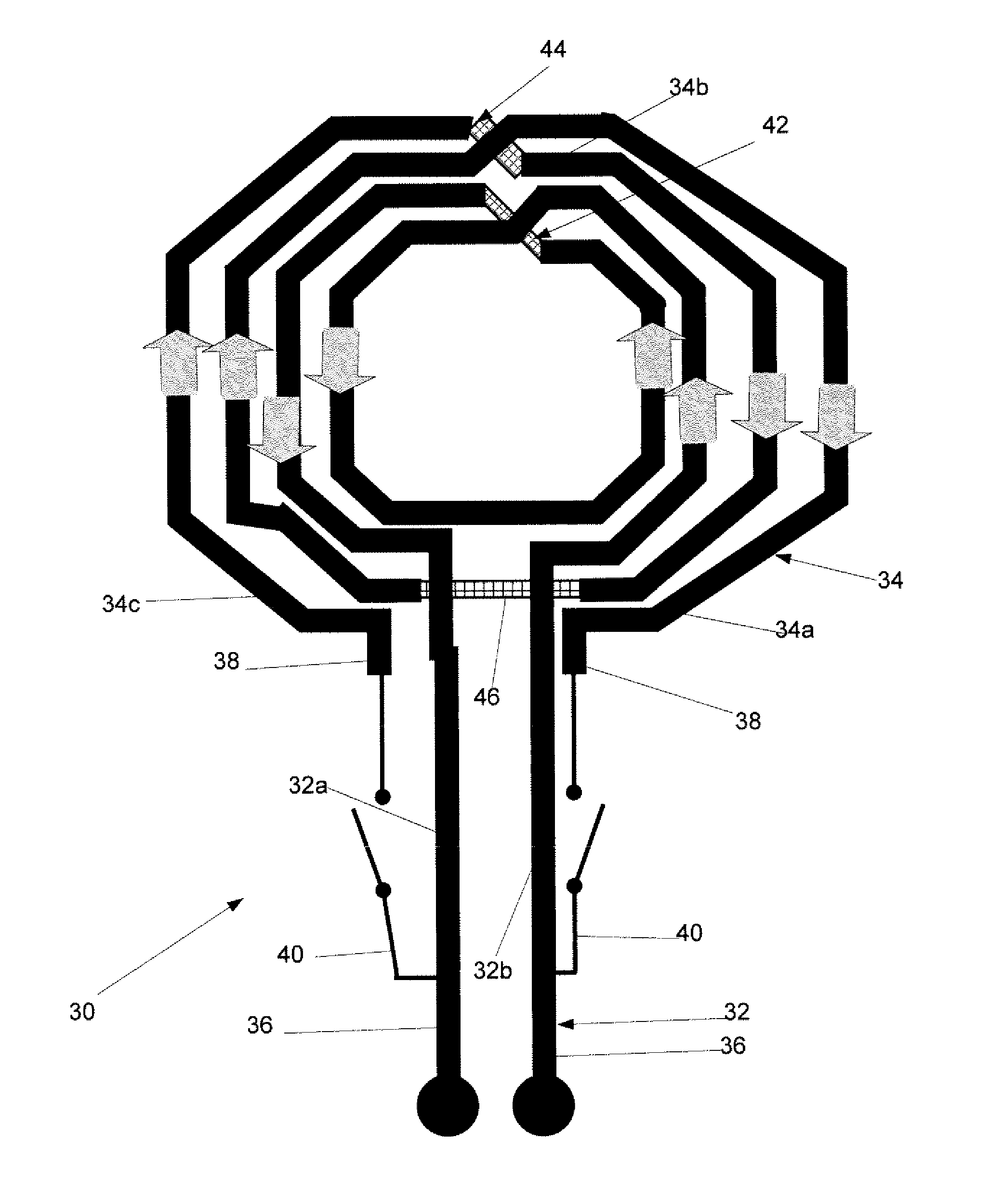
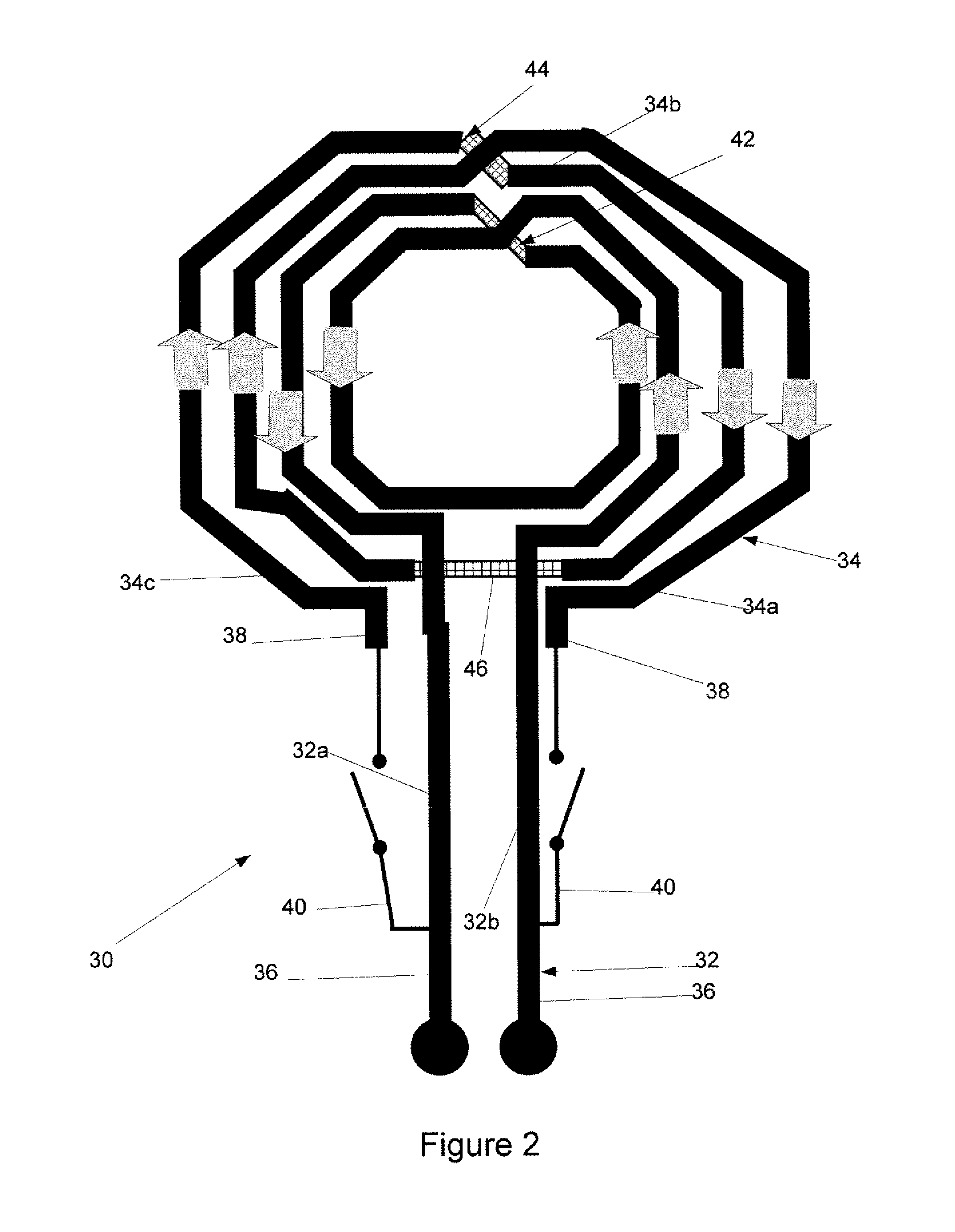
[0021]Generally, the present invention provides a method and system for implementing a variable inductor for an integrated circuit.

[0022]Turning to FIG. 2, a first embodiment of a variable inductor in accordance with the invention is shown. The variable inductor 30 comprises a primary conductor 32 and a secondary conductor 34. The primary conductor 32 and secondary conductor 34 are preferably differential inductors. Ends 36 of the primary conductor 32 are operatively connected to ends 38 of the secondary conductor 34 via a pair of switches 40.

[0023]The primary conductor 32 comprises two sections 32a and 32b connected together by an underpass 42 while the secondary connector 34 comprises three sections 34a, 34b and 34c which are connected by a pair of underpasses 44 and 46. In operation, if the pair of switches 40 are open, there is no current flowing through the secondary conductor 34. As there is only current flowing through the primary conductor 32, the variable inductor 30 provid...


PUM


Abstract

The present invention is directed at an inductor which is capable of providing a variable inductance. The variable inductor is typically mounted/stored on an integrated circuit chip to provide continuous or multiple variable inductor values for wireless applications and the like.

Description

FIELD OF THE INVENTION[0001]The present invention relates generally to integrated circuits. More particularly, the present invention relates to a variable inductor for an integrated circuit.BACKGROUND OF THE INVENTION[0002]In the field of integrated circuits, technology is rapidly improving and new methods of implementing analog circuit blocks on integrated circuits are being realized. Furthermore, components of these analog circuit blocks are consistently being upgraded to improve their operational capacity. One such component is a variable inductor. Various examples of variable inductors are currently known and described in US Patent Application No. 2004 / 0140528 entitled “STACKED VARIABLE INDUCTOR” which was published on Jul. 22, 2004 and US Patent Application No. 2005 / 0068146 entitled “VARIABLE INDUCTOR FOR INTEGRATED CIRCUIT AND PRINTED CIRCUIT BOARD” which was published on Mar. 31, 2005,[0003]FIG. 1 shows a prior art embodiment of a variable inductor 10. The variable inductor 1...

Claims


Application Information

Patent Timeline
IPC IPC(8): H01F29/06H01F5/00
CPCH01F27/2804H01F21/12
Inventor KHAJEHPOUR, JAVAD
Owner SIRIFIC WIRELESS CORP
Why Eureka
Try Eureka