

Antenna for mobile communication terminals
a mobile communication terminal and antenna technology, applied in the field of radio frequency antennas, can solve the problem that the pifa pair of slotted antennas is less effective for telecommunications handsets whose covers are covered
- Summary
- Abstract
- Description
- Claims
- Application Information
AI Technical Summary
Benefits of technology
Problems solved by technology
Method used
Image

Examples
Embodiment Construction
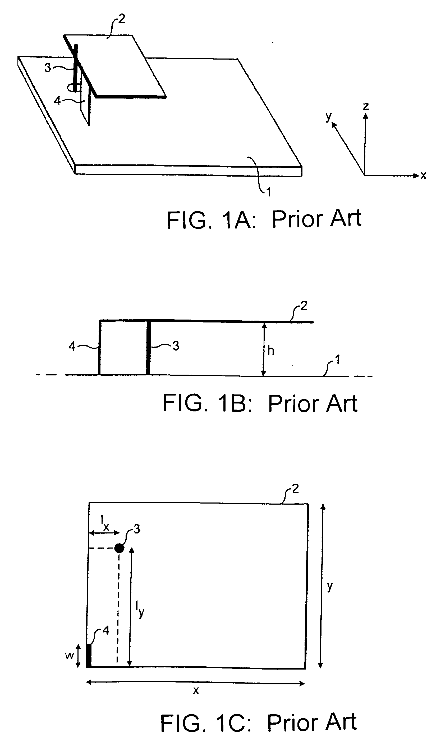
[0021]The inventors of the present invention have found that significant improvements in antenna performance may be achieved, compared with a standard PIFA, by introducing an additional ground plane between the ground plane 1 of FIG. 1A and the conducting sheet 2.
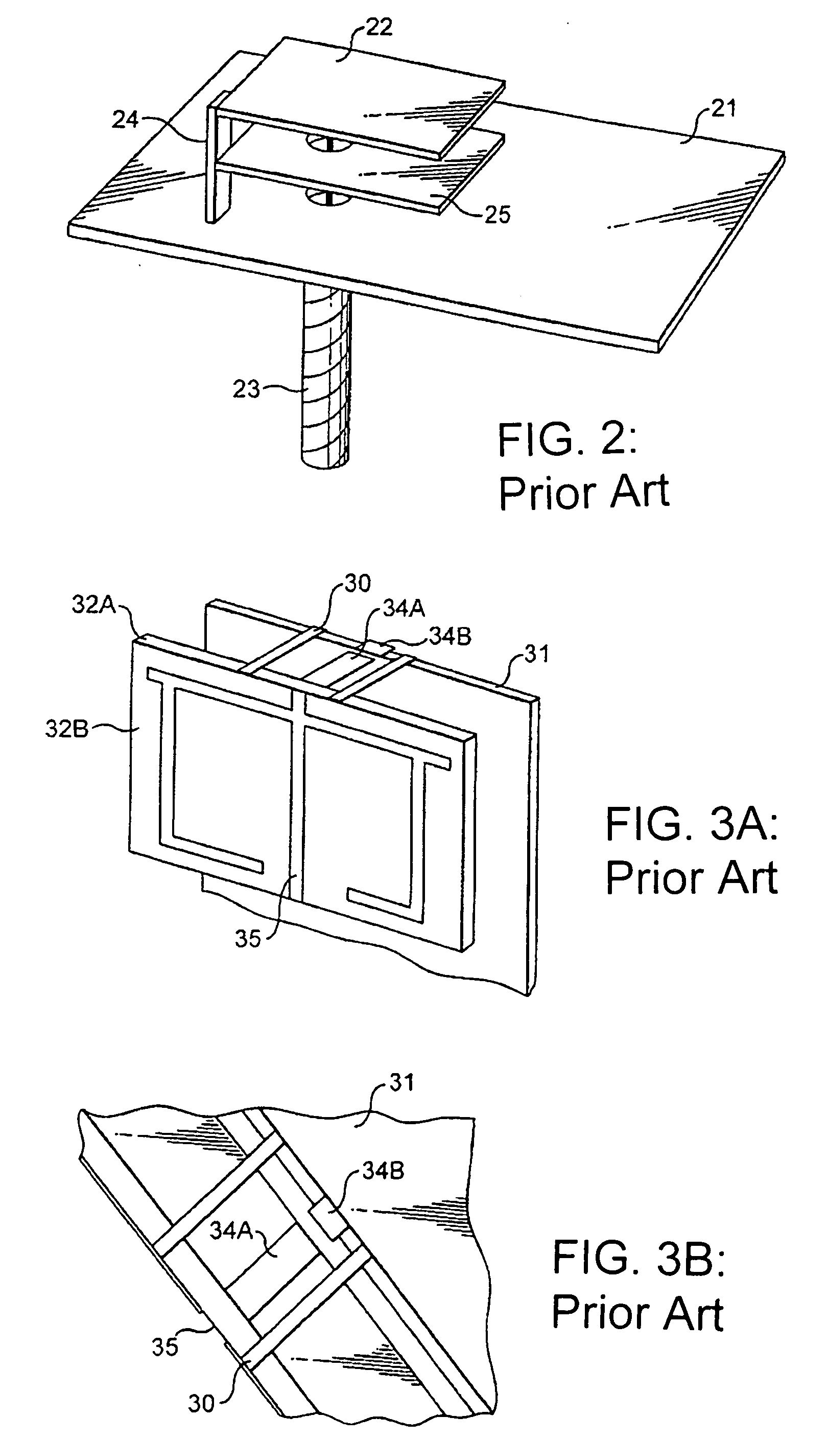
[0022]In general, if two or more ground connections are made between a conducting plate and ground, then the plate will act as an additional ground plane rather than as a parasitic resonator such as that shown as 25 in the prior art structure illustrated in FIG. 2. As discussed further below, the positions of the ground connections affect the frequency at which the additional ground plane will provide resonance.
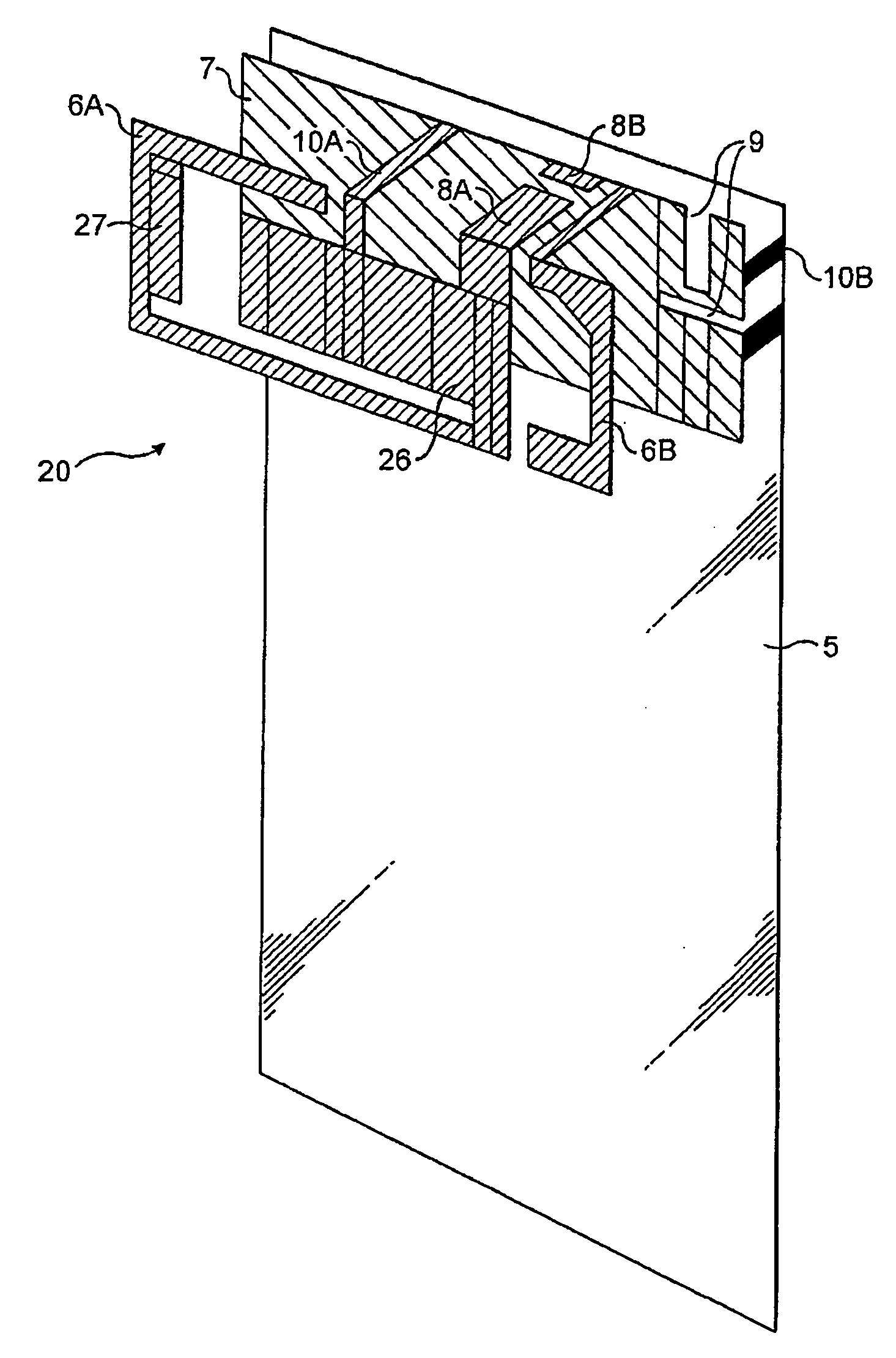
[0023]An exemplary arrangement is shown in FIG. 4A, where a circuit board (for example, a printed wiring board) 5 acts as the antenna's main ground plane. Alternatively, an RF shielding can or any metal part of mobile handset may be used in place of the printed wiring board (PWB) as the antenna's ground plane. Positi...
PUM
 Abstract
Description
Claims
Application Information