Electrical connector having contact modules

a technology of contact modules and electrical connectors, which is applied in the direction of coupling device connections, coupling contact members, securing/insulating couplings, etc., and can solve the problems of more complicated signal trace routing, more expensive manufacturing, and undesirable thick circuit boards

Active Publication Date: 2016-08-09
TYCO ELECTRONICS LOGISTICS AG (CH)
View PDF12 Cites 57 Cited by
  • Summary
  • Abstract
  • Description
  • Claims
  • Application Information

AI Technical Summary

Problems solved by technology

Signal trace routing is further complicated when the electrical terminal tails at the connector footprint are arranged in various groupings or arrays that do not provide designated routes for signal traces between the corresponding vias that engage the electrical terminal tails.
However, thick circuit boards are undesirable and more expensive to manufacture than thinner boards having fewer layers.

Method used


Image

  • Electrical connector having contact modules
  • Electrical connector having contact modules
  • Electrical connector having contact modules

Examples


Embodiment Construction

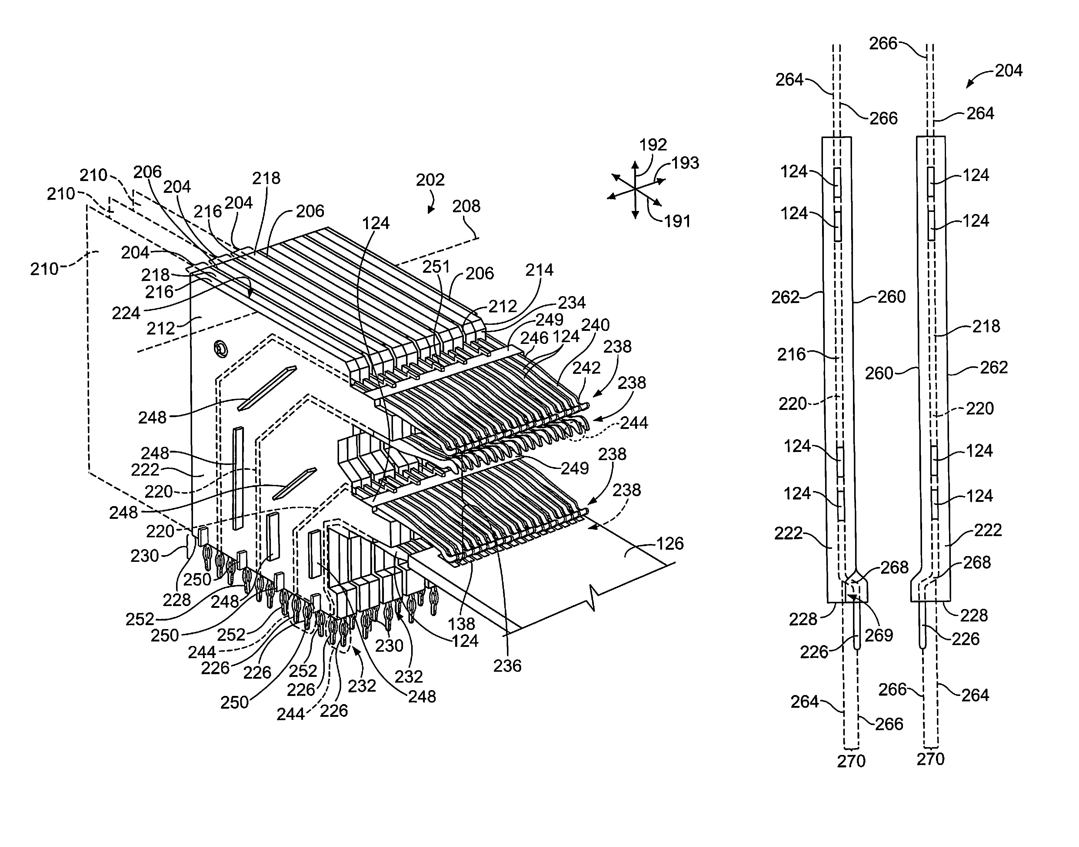
[0014]Embodiments set forth herein include electrical connectors that mount to circuit boards. The electrical connectors provide spaces for signal trace routes along the circuit boards away from the footprints of the electrical connectors. The electrical connectors described herein reduce the need to add additional layers to and / or increase the area of the circuit boards upon which the electrical connectors are mounted.

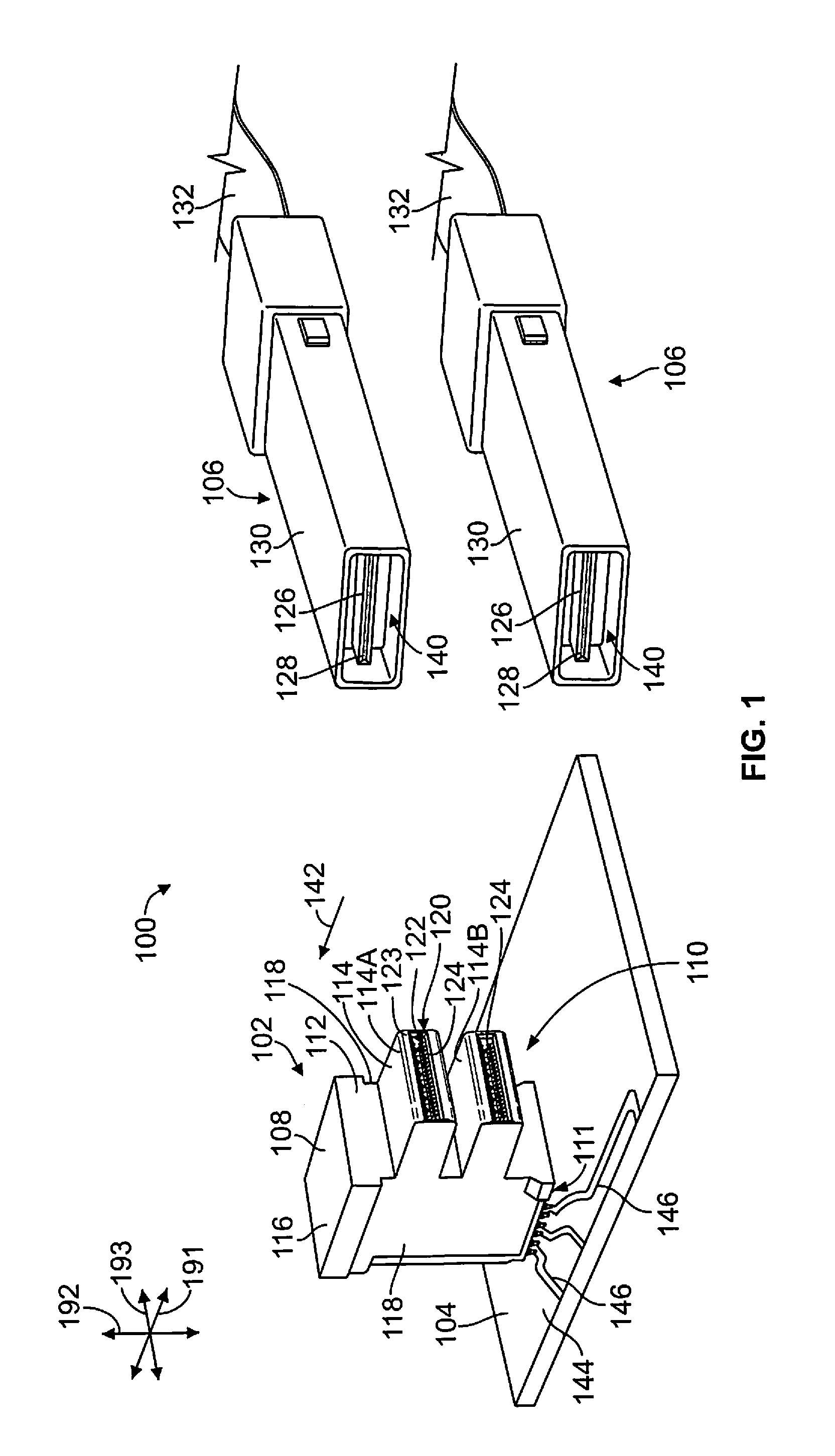
[0015]FIG. 1 is a perspective view of an electrical system 100 in accordance with an exemplary embodiment. The electrical system 100 includes an electrical connector 102 that is mounted on a host circuit board 104. The electrical system 100 further includes pluggable modules 106 that are configured to mate with the electrical connector 102 to electrically connect the pluggable modules 106 to the electrical connector 102. Signals are transmitted between the pluggable modules 106 and the circuit board 104 through the electrical connector 102. Two pluggable modules 106 a...


PUM


Abstract

An electrical connector includes a housing and a plurality of contact modules and ground plates held by the housing. Each contact module includes left and right signal wafers stacked next to each other along a stack axis. The signal wafers include electrical terminals held by a dielectric body. The electrical terminals have mounting contacts protruding from the dielectric body at a mounting face of the housing. The electrical terminals of at least one of the signal wafers in each contact module are jogged toward the other signal wafer such that the mounting contacts of each contact module align in a column. Each of the ground plates is disposed along an outer side of a corresponding contact module.

Description

BACKGROUND OF THE INVENTION[0001]The subject matter herein relates generally to electrical connectors that have contact modules.[0002]Some electrical systems utilize an electrical connector, such as a receptacle or header connector, to interconnect a circuit board and at least one pluggable module. The electrical connector is mounted to the circuit board. For example, the electrical connector includes electrical terminals with tails that terminate to conductive vias on the circuit board. The circuit board has signal traces routed from the conductive vias. An opposite end of the electrical terminals may extend into a mating interface of the electrical connector for electrical connection to a circuit card or electrical contacts of a corresponding pluggable module mated to the electrical connector. A conductive signal pathway is formed that includes the circuit card or an electrical contact of the pluggable module, the electrical terminal of the electrical connector that engages the ci...

Claims


Application Information

Patent Timeline
Patent Type & Authority Patents(United States)
IPC IPC(8): H01R13/648H01R13/514H01R13/6467H01R12/71H01R12/72H01R13/6471H01R13/6587H01R12/58
CPCH01R13/6467H01R12/716H01R12/724H01R13/514H01R13/6471H01R13/6587H01R12/585H01R12/714H01R12/727H01R13/40H01R13/648
Inventor HELSTER, DAVID WAYNESHIELDS, LINDA ELLENPHILLIPS, MICHAEL JOHNCHAMPION, BRUCE ALLENPATEL, SANDEEP
Owner TYCO ELECTRONICS LOGISTICS AG (CH)
Why Eureka
Try Eureka