Antenna apparatus and portable wireless device using the same

a portable wireless and antenna technology, applied in the direction of resonant antennas, independent non-interacting antenna combinations, antenna earthings, etc., can solve the problems of property deterioration, difficulty in adjusting the element itself by coupling, etc., to reduce the isolation property, and reduce the coupling between antenna elements

Inactive Publication Date: 2006-08-17
PANASONIC CORP
View PDF12 Cites 58 Cited by
  • Summary
  • Abstract
  • Description
  • Claims
  • Application Information

AI Technical Summary

Benefits of technology

[0007] The invention provides an antenna apparatus and a portable wireless device using the same, in which a coupling between antenna elements is reduced and an isolation property is improved even when frequencies of antenna elements are close or overlapped.
[0008] The antenna apparatus of the invention includes a ground board, a first antenna element corresponding to a first frequency band, a second antenna element corresponding to a second frequency band in the vicinity of, or overlapped with the first frequency band, a first power feeding part connecting the ground board to the first antenna element and a second power feeding part connecting the ground board to the second antenna element, having a structure in which the first antenna element is arranged in a direction at an angle of an integer multiple of 90 degrees with respect to a long edge of the ground board, and the second antenna element is arranged in parallel with the long edge of the ground board. According to this, the antenna apparatus and the portable wireless device using the same, in which the coupling between antenna elements is reduced and the isolation property is improved can be provided.

Problems solved by technology

However, in the conventional antenna apparatus, plural antenna elements are simply arranged in a ground board, therefore, when frequencies of antenna elements are close or overlapped, problems of property deterioration by a coupling between elements, and difficulty in adjusting the element itself by the coupling can occur.

Method used


Image

  • Antenna apparatus and portable wireless device using the same
  • Antenna apparatus and portable wireless device using the same
  • Antenna apparatus and portable wireless device using the same

Examples


first embodiment

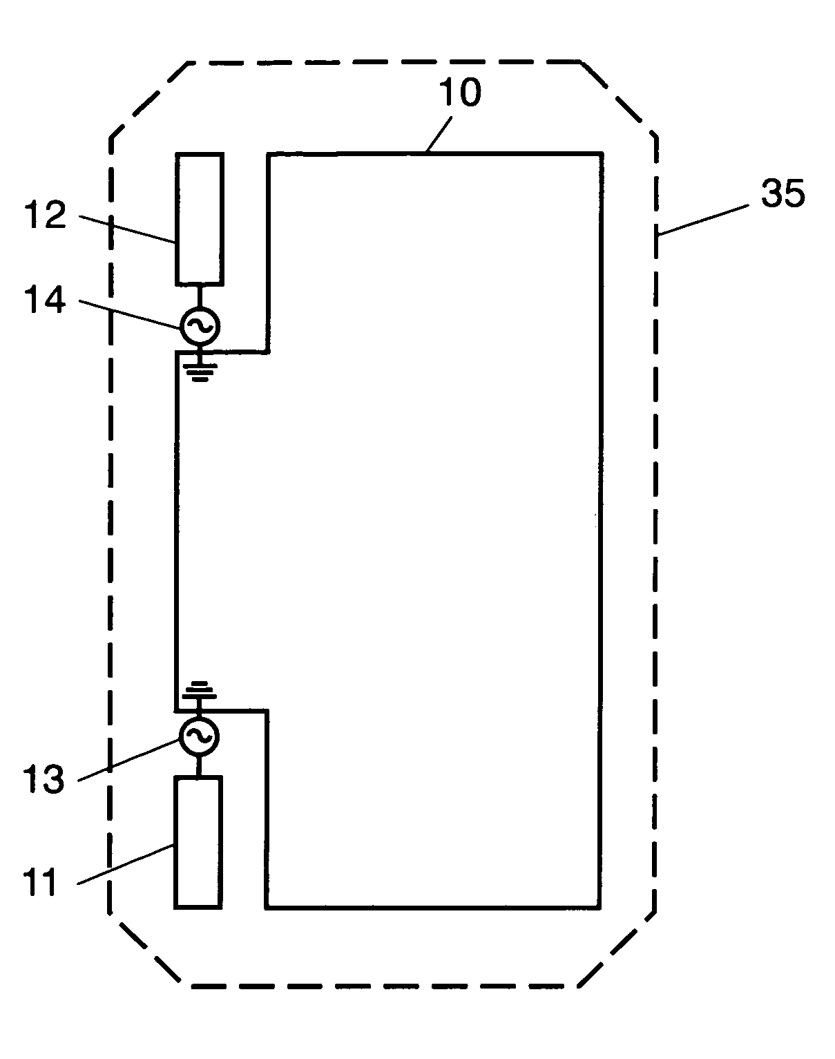
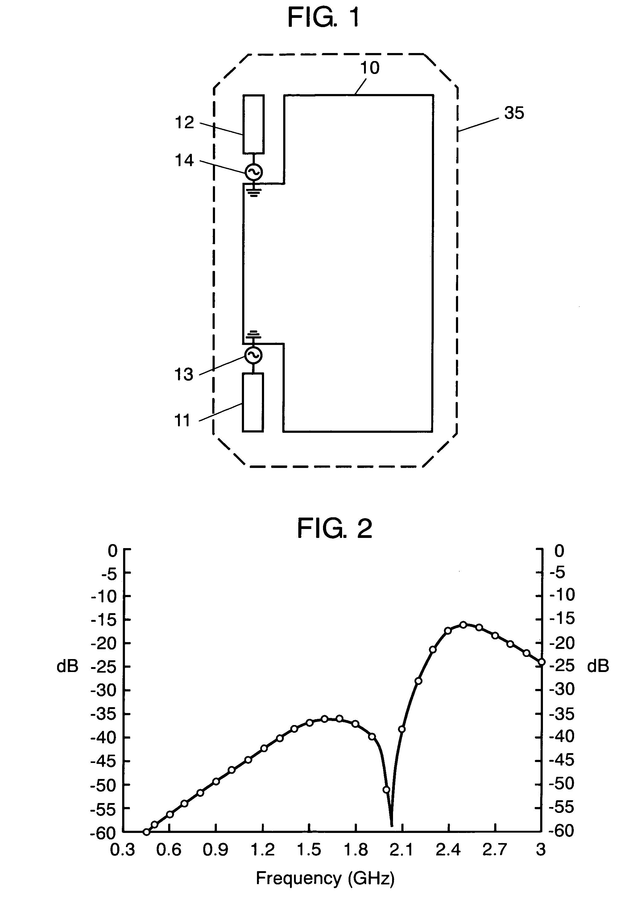
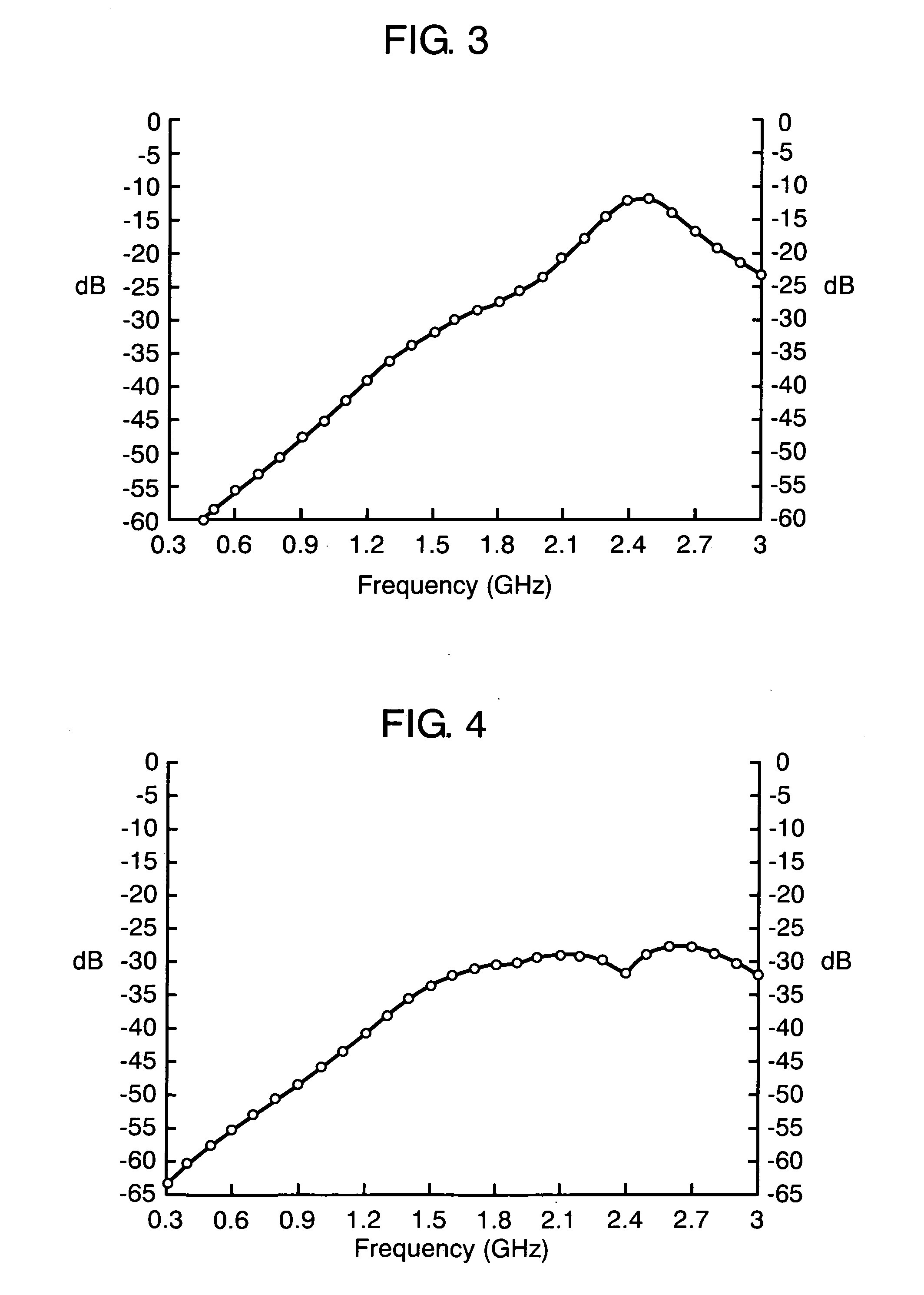
[0022]FIG. 1 is a view showing a structure of a portable wireless device including an antenna apparatus according to a first embodiment of the invention. FIG. 2 is a graph showing a transmission characteristic of the antenna apparatus according to the same embodiment. FIG. 3 is a graph showing a transmission characteristic of an antenna apparatus when two antenna elements are arranged to be orthogonal to a long edge of a ground board to be compared with the antenna apparatus according to the same embodiment. FIG. 4 is another graph showing the transmission characteristic according to the same embodiment.

[0023] In FIG. 1, portable wireless device 35 includes an antenna apparatus having ground board 10, first antenna element 11, second antenna element 12, first power feeding part 13 and second power feeding part 14. First antenna element 11 is arranged in a direction parallel to a long edge of ground board 10, having relation of 180 degrees with respect to second antenna element 12. ...

second embodiment

[0028]FIG. 5 is a view showing a portable wireless device including an antenna apparatus according to a second embodiment of the invention. In the embodiment, components having the same structures as the first embodiment are denoted by the same reference numerals and explanations thereof are omitted. In FIG. 5, first slit 15 is provided at a position corresponding to the length of approximately ¼ wavelength in a short edge at the side of antenna element 11 which is connected to ground board 10, and second slit 16 is provided at a position corresponding to the length of approximately ¼ wavelength in a short edge at the side of antenna element 12.

[0029] In the embodiment, by providing slits 15, 16 at the positions corresponding to the length of approximately ¼ wavelength in the short edges of ground board 10, the apparatus can be equivalent to the one whose short-edge length of ground board 10 is ¼ wavelength long, utilizing resonance by the slits, therefore, an isolation property ca...

third embodiment

[0030]FIG. 6 is a view showing a structure of a portable wireless device including an antenna apparatus according to a third embodiment of the invention. FIG. 7 is a view showing a structure of a portable wireless device including another antenna apparatus according to the same embodiment. In the embodiment, components having the same structures as the first embodiment are denoted by the same reference numerals and explanations thereof are omitted. In FIG. 6, ground board 10 has first cut-out portion 17 from a position corresponding to the length of approximately ¼ wavelength in a short edge at the side of antenna element 11 to be connected, and second cut-out portion 18 from a position corresponding to the length of approximately ¼ wavelength in a short edge at the side of antenna element 12, which have respectively step-shapes. In the embodiment, by providing cut-out portions 17, 18 at positions corresponding to the length of approximately ¼ wavelength in the short edges of ground...


PUM


Abstract

An antenna apparatus and a portable wireless device using the same are disclosed, in which a coupling between antenna elements is reduced and an isolation property is improved even when frequencies of antenna elements are close or overlapped. The antenna apparatus includes a ground board, a first antenna element corresponding to a first frequency band, a second antenna element corresponding to a second frequency band in the vicinity of, or overlapped with the first frequency band, a first power feeding part connecting the ground board to the first antenna element and a second power feeding part connecting the ground board to the second antenna element, in which the first antenna element is arranged in a direction at an angle of an integer multiple of 90 degrees with respect to a long edge of the ground board, and the second antenna element is arranged in parallel with the long edge of the ground board.

Description

BACKGROUND OF THE INVENTION [0001] 1. Field of the Invention [0002] The present invention relates to an antenna apparatus which corresponds to plural frequency bands and a portable wireless device using the same. [0003] 2. Description of the Related Art [0004] On a cellular phone as a major example of portable wireless devices used for mobile communication, installations of not only a function as a telephone but also communication system functions corresponding to various applications are proceeding As examples of such functions, FM radio reception, TV reception, a GPS function, compliance to Bluetooth standard, Wireless Local Area Network (WLAN) and the like can be cited. These systems differ from one another in frequency bands to be used and wireless circuitry, therefore, antenna elements corresponding to respective systems are required. [0005] A structure of a portable wireless device including a conventional antenna apparatus is shown in FIG. 12. Portable wireless device 105 inc...

Claims


Application Information

Patent Timeline
Patent Type & Authority Applications(United States)
IPC IPC(8): H01Q1/24
CPCH01Q1/243H01Q1/521H01Q9/40H01Q21/28
Inventor IGUCHI, AKIHIKOSATOH, YUKI
Owner PANASONIC CORP
Why Eureka
Try Eureka