Dielectric resonator device, high frequency filter, and high frequency oscillator

a technology of dielectric resonators and filters, which is applied in the direction of oscillator details, semiconductor devices, semiconductor/solid-state device details, etc., can solve the problems of increasing loss, deteriorating resonator sub-sections, and inability to increase the electric field intensity at the leading end of slot lines

Inactive Publication Date: 2004-02-05
MURATA MFG CO LTD
View PDF12 Cites 10 Cited by
  • Summary
  • Abstract
  • Description
  • Claims
  • Application Information

AI Technical Summary

Benefits of technology

[0012] According to the present invention, an excitation section can extend a slot into an opening of a resonator, and the excitation section can be disposed in a position in the opening of the resonator in which electric field intensity is strong. Accordingly, by inputting a high frequency signal having strong electric field intensity, for example, to a leading end (projecting end) of the excitation section, the resonator can be strongly excited, so that the coupling between the resonator and the slot line can be strengthened. Also, since each of the resonant mode of the resonator and the transmission mode of the slot resonator can be set to the TE mode, deterioration of no load Q of the resonator can be suppressed. Moreover, provision of the excitation section in the opening of the resonator can reduce the size of the entire device compared with the case of providing the excitation section outside the resonator.
[0014] According to the present invention, a position in the resonator in which the electric field is the maximum can be made close to a leading end of the excitation section which is a virtual open end. Thus, the coupling between the resonator and the slot line can be further strengthened.
[0018] According to the present invention, the leading end of the excitation section, which is formed by extension, at a leading end of the T-branch line, can be used as a virtual open end. Thus, the leading end of the excitation section can be disposed in a position in which electric field is strong in the resonator, so that the coupling between the resonator and the slot line can be further strengthened.
[0020] According to the present invention, the coupling between the resonator and the slot line in the dielectric resonator device can be strengthened, so that the frequency range of the high frequency filter using the dielectric resonator device can be expanded.
[0022] According to the present invention, the function of line conversion can be built into the high frequency filter, thus making the high frequency filter highly functional. Also, compared with the case of providing a line converter separately from the high frequency filter, the line converter can be omitted, thus reducing the size of the entire device.
[0024] According to the present invention, the coupling between the resonator and the slot line in the dielectric resonator device can be strengthened, thus enabling a reduction in phase noise in the high frequency oscillator using the dielectric resonator device, an increase in frequency modulation width, and an increase in oscillating output.

Problems solved by technology

Accordingly, when strong coupling is established between the TE010-mode resonator or the like and the coplanar line, a problem occurs in that no load Q (Q.sub.0) of the resonator deteriorates, thus increasing the loss.
Thus, electric field intensity at the leading end of the slot line cannot be increased, so that strong coupling between the slot resonator and the slot line cannot be obtained.

Method used


Image

  • Dielectric resonator device, high frequency filter, and high frequency oscillator
  • Dielectric resonator device, high frequency filter, and high frequency oscillator
  • Dielectric resonator device, high frequency filter, and high frequency oscillator

Examples


first embodiment

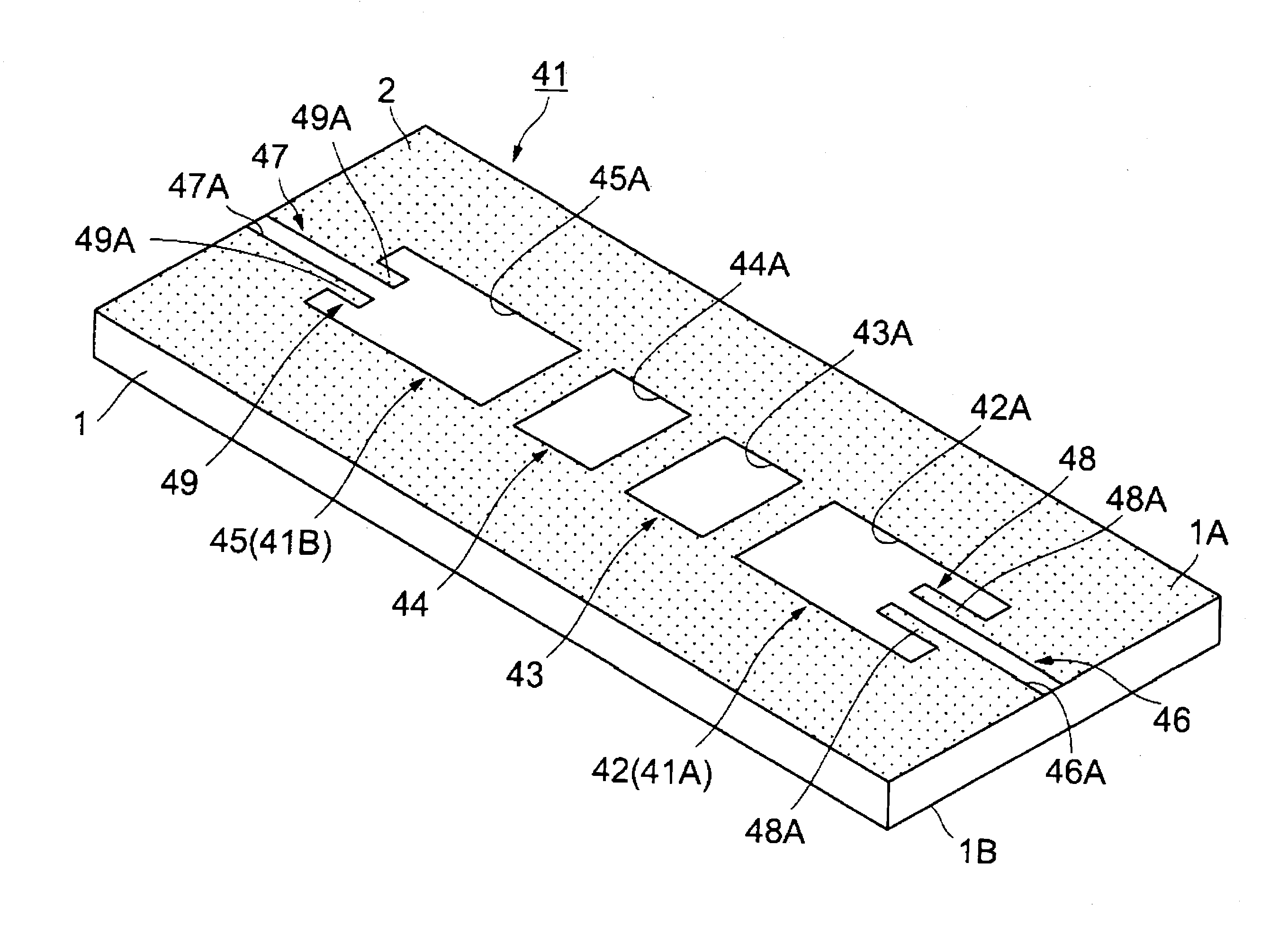
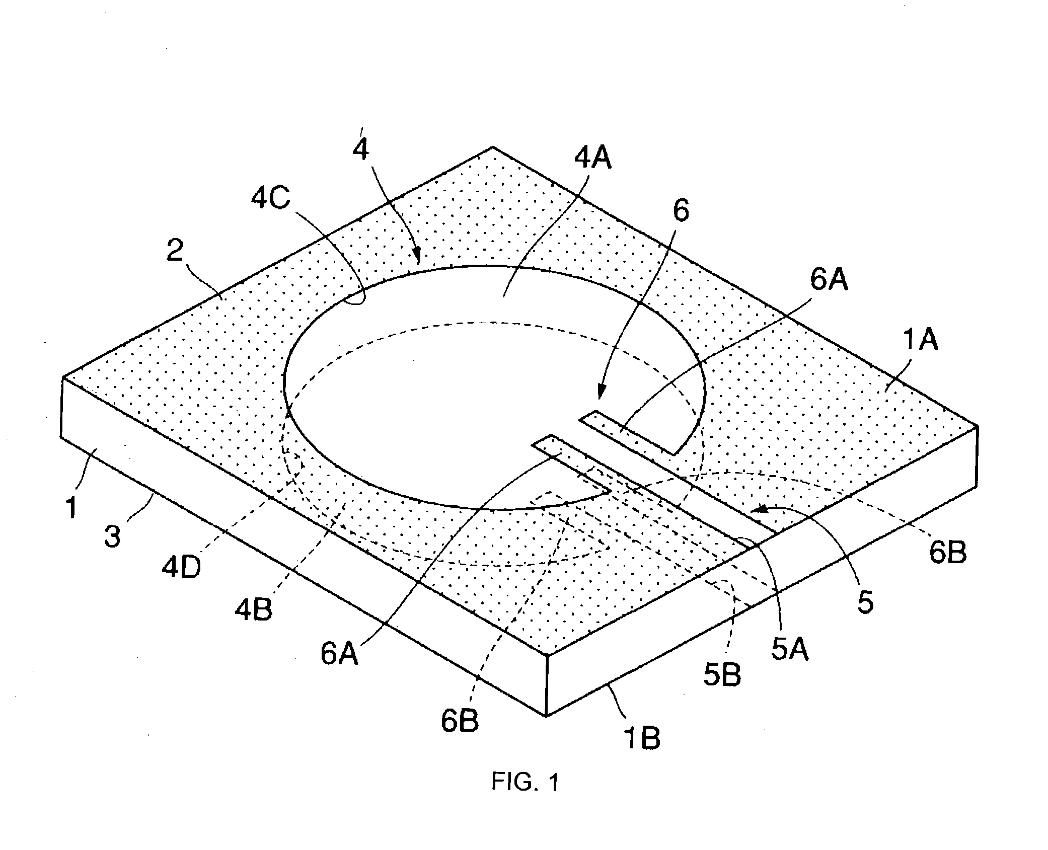
[0044] FIGS. 1 to 3 show a dielectric resonator device according to the present invention. In FIGS. 1 to 3, a dielectric substrate 1 has a substantially quadrangular planar shape. Dielectric material for the dielectric substrate 1 is resin material, ceramic material, or composite material formed by mixing the resin material and the ceramic material and burning the mixture. The dielectric substrate 1 has, for example, a thickness t set at 0.6 mm (t=0.6 mm) and relative dielectric constant .epsilon.r set at approximately 24 (.epsilon.r=24).

[0045] The dielectric substrate 1 has electrode films 2 and 3 respectively formed on the front surface 1A and back surface 1B thereof. The electrode films 2 and 3 are formed by using, for example, lithography technology or the like to fine pattern both surfaces with conductive metal thin films of gold, silver, copper, etc.

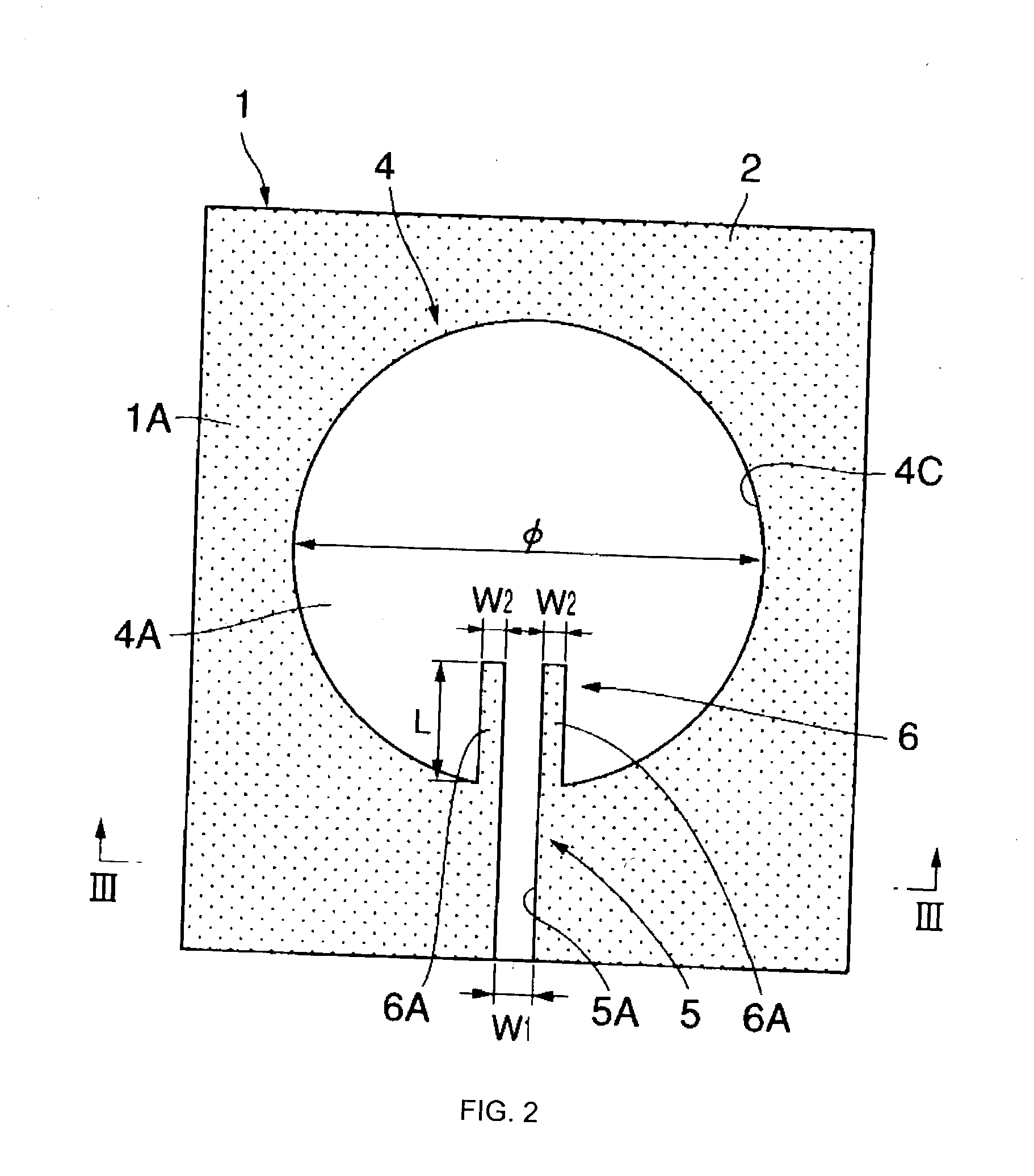
[0046] A circular TE010-mode resonator 4 in the center of the dielectric substrate 1 is formed by circular openings 4A and 4B res...

second embodiment

[0075] The dielectric resonator device has the above-described structure. A TE-mode high frequency signal, transmitted through the slot line 22, is emitted from the end of the excitation section 23 into the PDTL resonator 21. This forms, in the PDTL resonator 21, an electric field E almost parallel to the width direction of the slot 22A and a magnetic field H surrounding the electric field E. The high frequency signal resonates, forming the TE mode.

[0076] Accordingly, also in the second embodiment, operation and advantages similar to those in the first embodiment can be obtained.

[0077] In the case of the PDTL resonator 21, as in the comparative example shown in FIG. 15, between the PDTL resonator 21 and the slot line 22, by providing an exciting slot portion 24 which has a width larger than that of the slot 22A, the amount of coupling between the PDTL resonator 21 and the slot line 22 can be also increased.

[0078] In this case, the exciting slot portion 24 is formed out of the PDTL ...

third embodiment

[0084] A circular resonator 31 is provided in the center of the dielectric substrate 1. The circular resonator 31 is formed by a circular opening 31A formed in an electrode film 2. In the circular resonator 31, when the wavelength of a high frequency signal corresponding to resonant frequency f0 in the dielectric substrate 1 is represented by .lambda.g, the diameter is set to a value approximately equal to wavelength .lambda.g. In the third embodiment, no electrode film is formed on the back surface 1B of the dielectric substrate 1.

[0085] A slot line 32 (another type of slot line) is a transmission line provided away from the circular resonator 31. The slot line 32 is formed by a groove slot 32A formed in an electrode film 2. The slot 32A leads in parallel with a tangent to the slot 32A.

[0086] A stub line 33 is a T-branch line branching off in a T-form from the slot line 32. The stub line 33 linearly leads from a position on the slot line 32 to the circular resonator 31, and is form...


PUM


Abstract

A dielectric resonator device includes a dielectric substrate. Electrode films are formed on the front and back surfaces of the dielectric substrate, respectively. A TE010-mode resonator is constituted by two circular openings which oppose each other and which are formed in the electrode films. Two opposing slots formed in the electrode films constitute a planar dielectric transmission line (PDTL). The PDTL is connected to the TE010-mode resonator. An excitation section is formed by extending two portions of each electrode film on two side of each slot into each opening.

Description

[0001] 1. Field of the Invention[0002] The present invention relates to a dielectric resonator device, a high frequency filter, and a high frequency oscillator which are suitable for use in high frequency electromagnetic waves (high frequency signals) such as microwaves and millimetric waves.[0003] 2. Description of the Related Art[0004] In general, a dielectric resonator device is known (e.g., Japanese Unexamined Patent Application Publication No. 11-239021, etc.) in which electrode films are provided on the front and back surfaces of a dielectric substrate, and a TE010-mode resonator is constituted by circular openings formed on the front and back surfaces of the dielectric substrate so as to oppose each other, with the dielectric substrate provided therebetween, and in which the front surface of the dielectric substrate is provided with a coplanar line connected to the TE010-mode resonator.[0005] In this example of the related art, a strip central conductor of the coplanar line w...

Claims


Application Information

Patent Timeline
Patent Type & Authority Applications(United States)
IPC IPC(8): H01P7/08H01P1/203H01P7/10
CPCH01P7/10H01P1/20318H03B5/18
Inventor MUKAIYAMA, KAZUTAKAMIKAMI, SHIGEYUKIMATSUZAKI, HIROYASUKOCHI, TETSUYABABA, TAKAHIROSAKAMOTO, KOICHIKOCHI, KIYOHARUKOCHI, AKIKO
Owner MURATA MFG CO LTD
Why Eureka
Try Eureka