Antenna having additional ground

a technology of additional ground and antenna elements, applied in the direction of antenna details, antenna earthings, antennas, etc., can solve the problems of interference of electromagnetic waves radiated from the antenna elements, difficult to implement the mimo antenna using the related art antenna, and narrow interval between the antenna elements, so as to avoid interference of electromagnetic waves radiated and free up installation and design of components.

Inactive Publication Date: 2008-06-05
SAMSUNG ELECTRONICS CO LTD
View PDF3 Cites 20 Cited by
  • Summary
  • Abstract
  • Description
  • Claims
  • Application Information

AI Technical Summary

Benefits of technology

[0012]The present invention has been provided to address the above-mentioned and other problems and disadvantages occurring in the related art arrangement, and an aspect of the present invention is to provide an antenna having an additional ground for avoiding interference of electromagnetic waves radiated from antenna elements, freeing installation and design of components when mounted in a small device, and retaining antenna characteristics after arranging with the ground in the design of the antenna having a plurality of the antenna elements.

Problems solved by technology

However, the MIMO antenna requires smaller antenna elements to install the plurality of the antenna elements within a small terminal.
Thus, it is very difficult to implement the MIMO antenna using the related art antennas.
To install the MIMO antenna in the small terminal, the interval between the antenna elements is inevitably narrow.
In this case, the electromagnetic waves radiated from the antenna elements are subject to the interference.
However, when the slots are formed in the ground, it may be hard to mount other components or the positions for mounting other components may be quite restricted.
When the antenna is designed in that order, it is hard to retain the antenna characteristics after the arrangement with the ground.
This disadvantage is true for not only the MIMO antenna but an array antenna and dual or multiband antenna having a plurality of antenna elements.

Method used


Image

  • Antenna having additional ground
  • Antenna having additional ground
  • Antenna having additional ground

Examples


Embodiment Construction

[0034]Certain exemplary embodiments of the present invention will now be described in greater detail with reference to the accompanying drawings.

[0035]In the following description, the same drawing reference numerals are used to refer to the same elements, even in different drawings. The matters defined in the following description, such as detailed construction and element descriptions, are provided as examples to assist in a comprehensive understanding of the invention. Also, well-known functions or constructions are not described in detail, since they would obscure the invention in unnecessary detail.

[0036]While a multiple input multiple output (MIMO) antenna is illustrated by way of example, the present invention is applicable to an array antenna and dual or multiband antenna having a plurality of antenna elements.

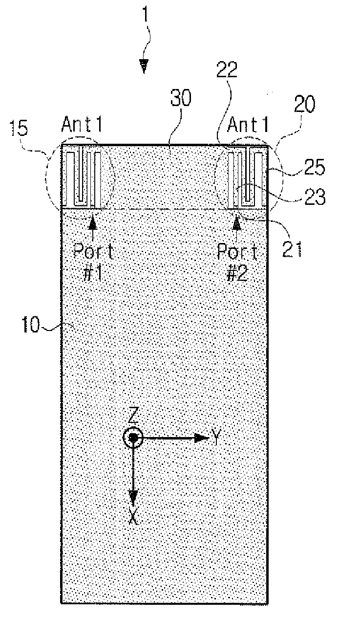
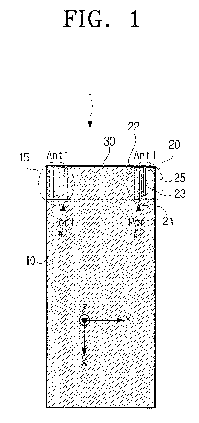
[0037]FIG. 1 is a plane view of an antenna having an additional ground according to one embodiment of the present invention.

[0038]The antenna 1 includes a first ground...


PUM


Abstract

An antenna having an additional ground, includes a first ground which is formed in one side of a substrate; a plurality of antenna elements which are formed symmetrically with respect to each other and spaced apart from one end of the first ground; and a second ground which is interposed between the plurality of the antenna elements and integrally formed with the first ground. Accordingly, the deterioration of the antenna characteristics can be minimized even after the arrangement of the antenna elements with the ground, and the antenna can be miniaturized and easily fabricated in a two-dimensional structure. Furthermore, the electromagnetic wave interference can be minimized between the antenna elements.

Description

CROSS-REFERENCE TO RELATED APPLICATIONS[0001]This application claims priority from Korean Patent Application No. 2006-122156 filed on Dec. 5, 2006 in the Korean Intellectual Property Office, the entire disclosure of which is incorporated herein by reference.BACKGROUND OF THE INVENTION[0002]1. Field of the Invention[0003]Methods consistent with the present invention relate to an antenna having an additional ground. More particularly, the present invention relates to an antenna having an additional ground, which can minimize antenna characteristic deterioration after arranging antenna elements with the ground, miniaturizing the antenna size, and minimizing electromagnetic wave interference between the antenna elements.[0004]2. Description of the Related Art[0005]In response to demands for high quality multimedia services using the wireless mobile communication technology, a next generation radio transmission technique is required to transfer more data at a higher rate with a lower err...

Claims


Application Information

Patent Timeline
Patent Type & Authority Applications(United States)
IPC IPC(8): H01Q1/48
CPCH01Q1/243H01Q21/28H01Q1/521H01Q1/48
Inventor MOON, YOUNG-MINKIM, YOUNG-EILPARK, SE-HYUNMIN, KYEONG-SIK
Owner SAMSUNG ELECTRONICS CO LTD
Why Eureka
Try Eureka