Optical Fibre Switch

a technology of optical fibre switch and optical fiber, applied in the field of switching, can solve the problems of slow switching action and system prone to failure, and achieve the effect of high electromechanical coupling coefficien

Inactive Publication Date: 2008-06-05
AUCKLAND UNISERVICES LTD
View PDF37 Cites 15 Cited by
  • Summary
  • Abstract
  • Description
  • Claims
  • Application Information

AI Technical Summary

Benefits of technology

[0012]The piezoelectric material may be a piezoelectric ceramic material having a high electromechanical coupling coefficient. Preferably, the piezoelectric ceramic material is lead zirconate titanate (PZT) with or without doping.

Problems solved by technology

These are complex systems and, due to the fact that mechanically moving parts are used, switching action is slow and the systems are susceptible to failures.

Method used


Image

  • Optical Fibre Switch
  • Optical Fibre Switch
  • Optical Fibre Switch

Examples


Embodiment Construction

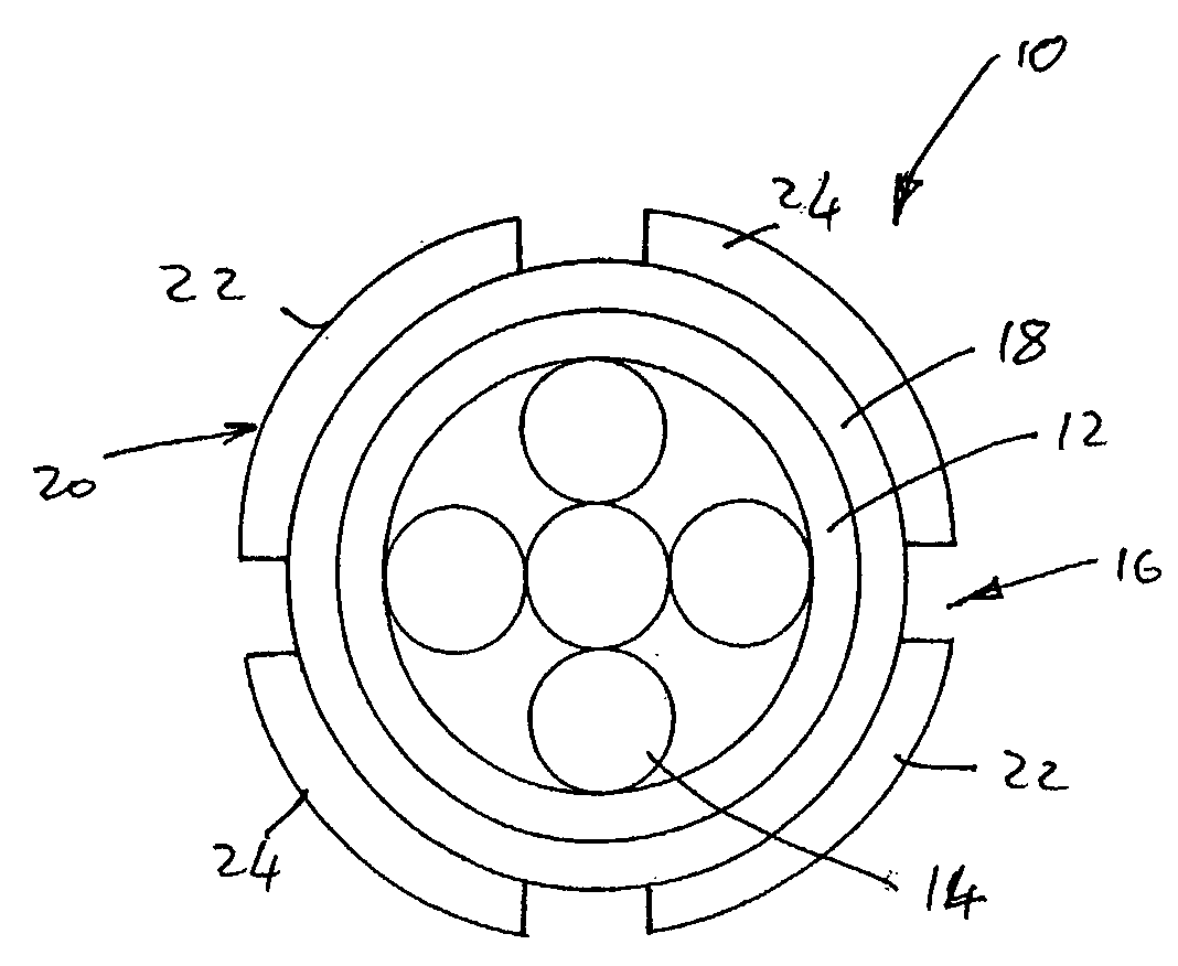
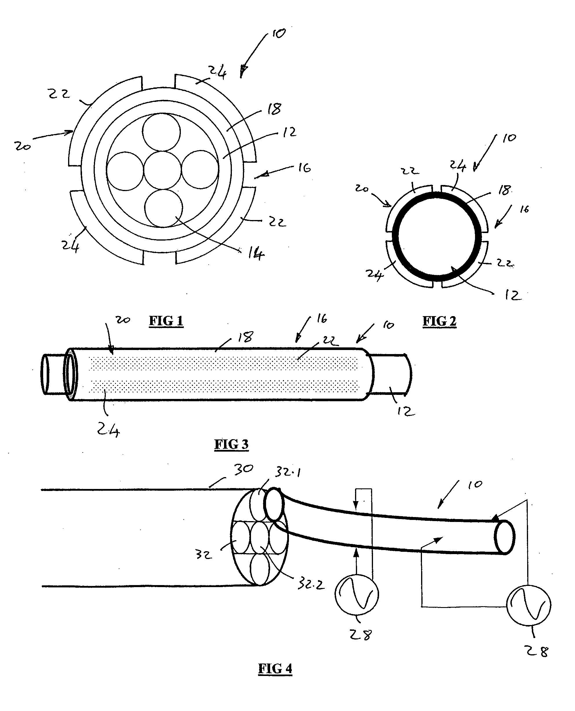
[0035]In the drawings, reference number 10 generally designates an optical fibre switch, in accordance with embodiments of the invention.

[0036]The switch 10 includes an optical fibre conduit 12. In the embodiment of the invention illustrated in FIG. 1 of the drawings, the conduit 12 surrounds a bundle of optical fibres 14. In the embodiment of the invention illustrated in FIG. 2 of the drawings, the optical fibre conduit 12 is a single optical fibre conduit.

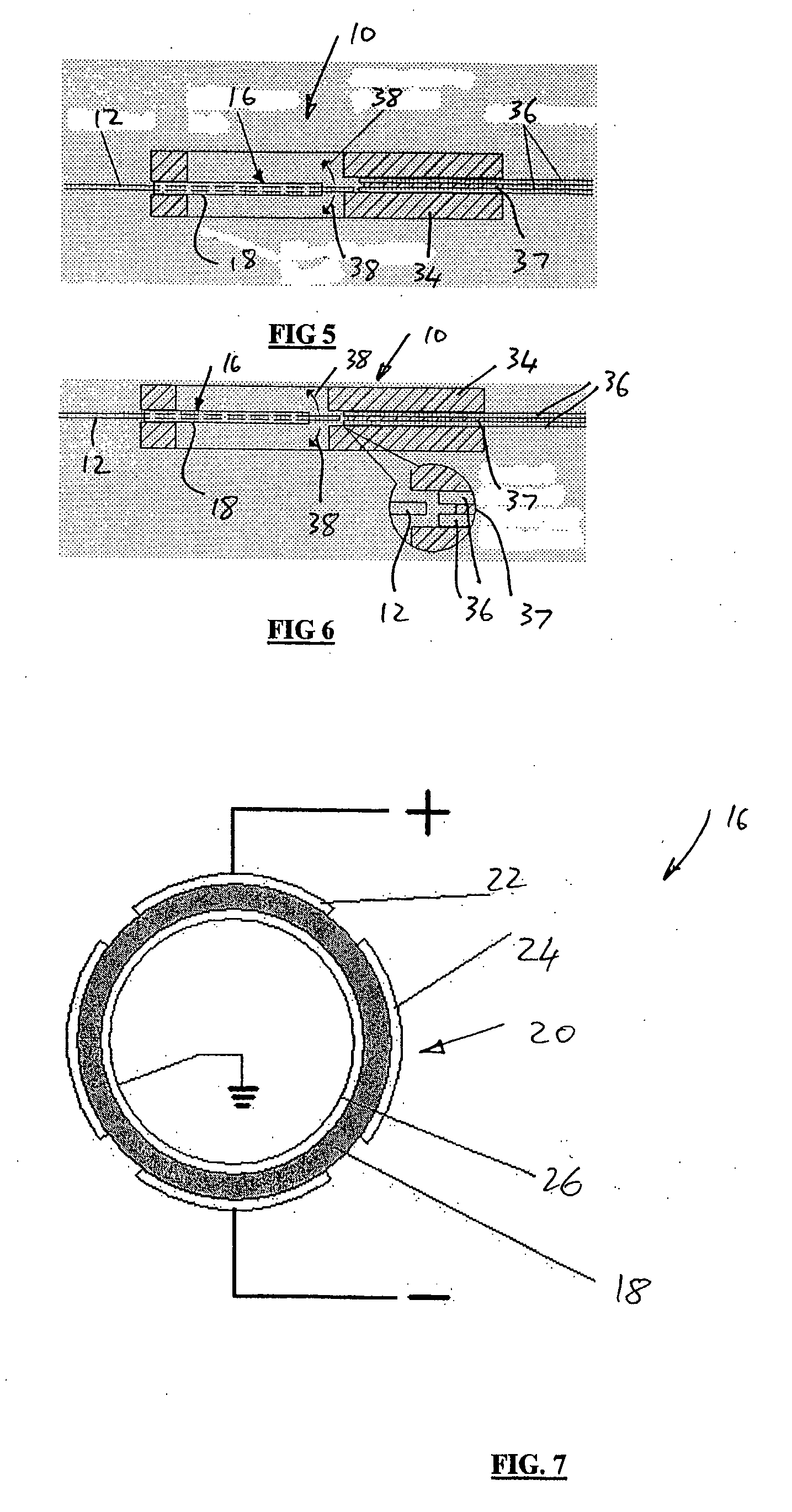
[0037]A transducer 16 is carried on the conduit 12, the transducer 16 converting input electrical energy into mechanical energy. More particularly, the transducer comprises a sleeve 18 of piezoelectric material applied to the conduit 12. The sleeve 18 of the transducer 16 is applied by way of applying a coating of the material on to an external surface of the conduit 12. Instead, the sleeve 18 of the transducer 16 is applied by way of a tube of, or containing, piezoelectric material, the tube being placed about the conduit 12.

[00...


PUM


Abstract

An optical fibre switch (10) includes an optical fibre conduit (12). A transducer (16) is carried on the conduit (12), the transducer (16) converting input energy of one form into mechanical energy so that the application of an external stimulus causes a change in condition of the transducer (16) which imparts that change in condition to the conduit (12). An input energy applying arrangement (20) is arranged on the transducer (16) for applying the external stimulus.

Description

CROSS-REFERENCE TO RELATED APPLICATIONS[0001]The present application claims priority from New Zealand Provisional Patent Application No 534883 filed on 24 Aug. 2004, the contents of which are incorporated herein by reference.FIELD OF THE INVENTION[0002]This invention relates to switching. More particularly, the invention relates to switching in optical fibres and, more specifically, to an optical fibre switch.BACKGROUND TO THE INVENTION[0003]Optical fibre signal transmission has become a critical part of the telecommunications industry, particularly in areas where signals may be susceptible to noise. During signal transmission, it may be necessary for the optical beam to be switched between a number of optical fibres in a transmission path. Optical fibre switching involves mechanically operated systems using mirrors to reflect light and, in so doing, change the light paths. These are complex systems and, due to the fact that mechanically moving parts are used, switching action is sl...

Claims


Application Information

Patent Timeline
Patent Type & Authority Applications(United States)
IPC IPC(8): G02B6/35H01L41/09H01L41/187
CPCG02B6/3502G02B6/3556H01L41/0966G02B6/358H01L41/094G02B6/3578H10N30/2042H10N30/2046
Inventor YOO, JU HYUNGAO, WEI
Owner AUCKLAND UNISERVICES LTD
Why Eureka
Try Eureka