Injection moldable composite gable vent

a composite gable vent and injection molding technology, which is applied in the direction of special door/window arrangement, building roof, doors/windows, etc., can solve the problems of slowing down a remodeling project, taking extra time to order and receive, and high cost of special order vents, etc., to achieve the effect of convenient molding

Inactive Publication Date: 2008-06-12
BLUEGRASS PRODS
View PDF16 Cites 4 Cited by
  • Summary
  • Abstract
  • Description
  • Claims
  • Application Information

AI Technical Summary

Problems solved by technology

Specially ordered vents are very expensive.
It also takes extra time to order and receive these.
This can slow down a remodeling project.
This post extrusion processing significantly increases the cost of the vent panels.

Method used


Image

  • Injection moldable composite gable vent
  • Injection moldable composite gable vent
  • Injection moldable composite gable vent

Examples


Embodiment Construction

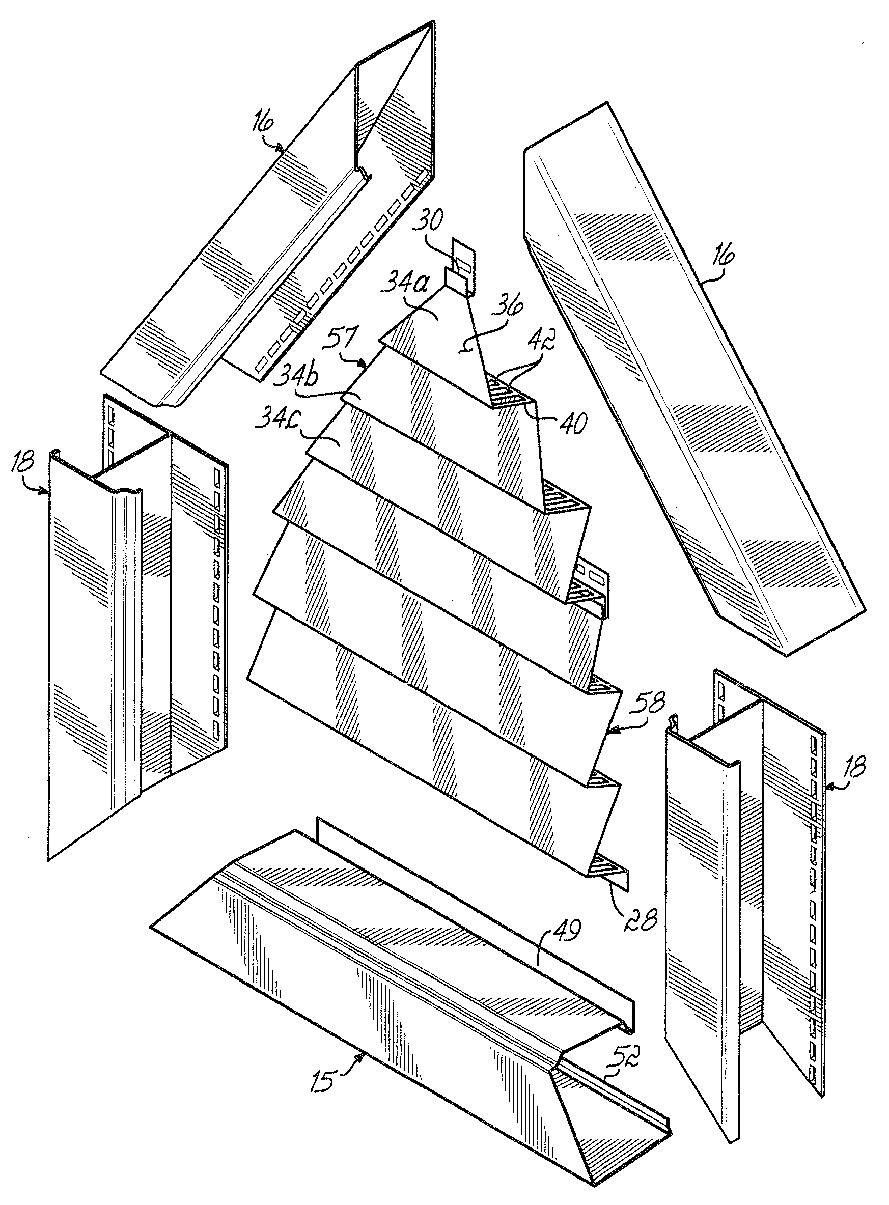
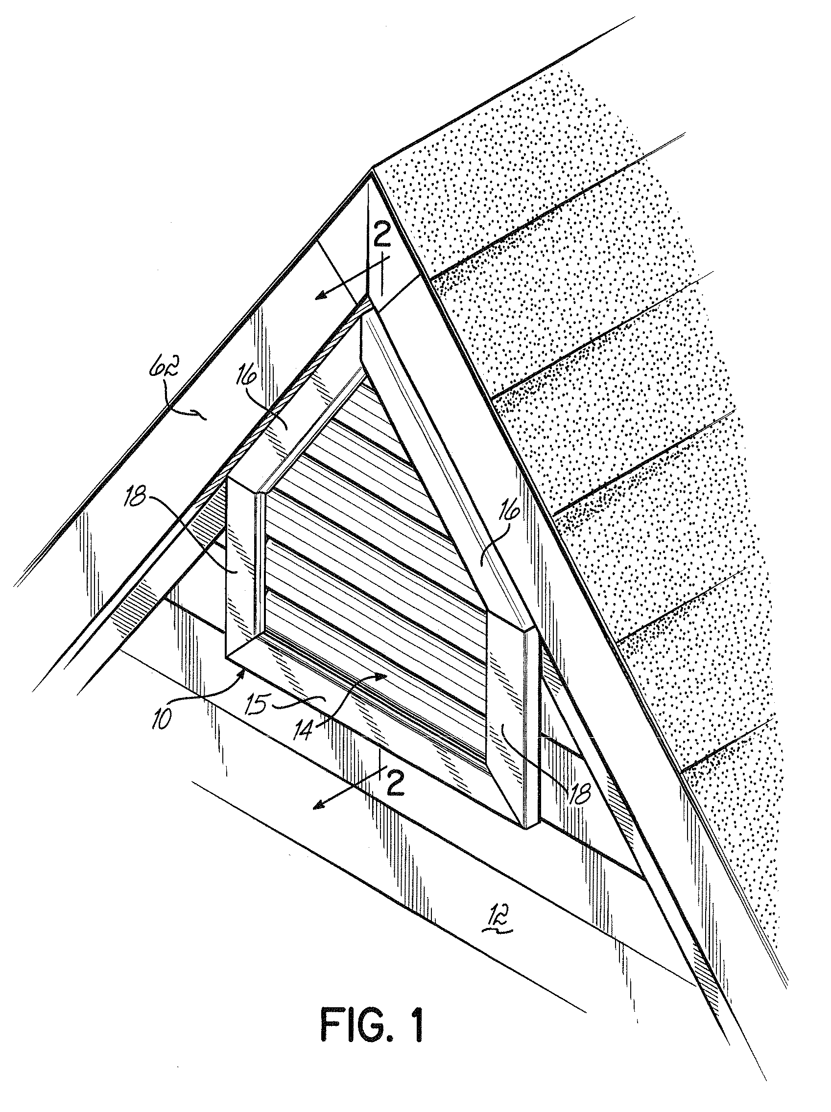
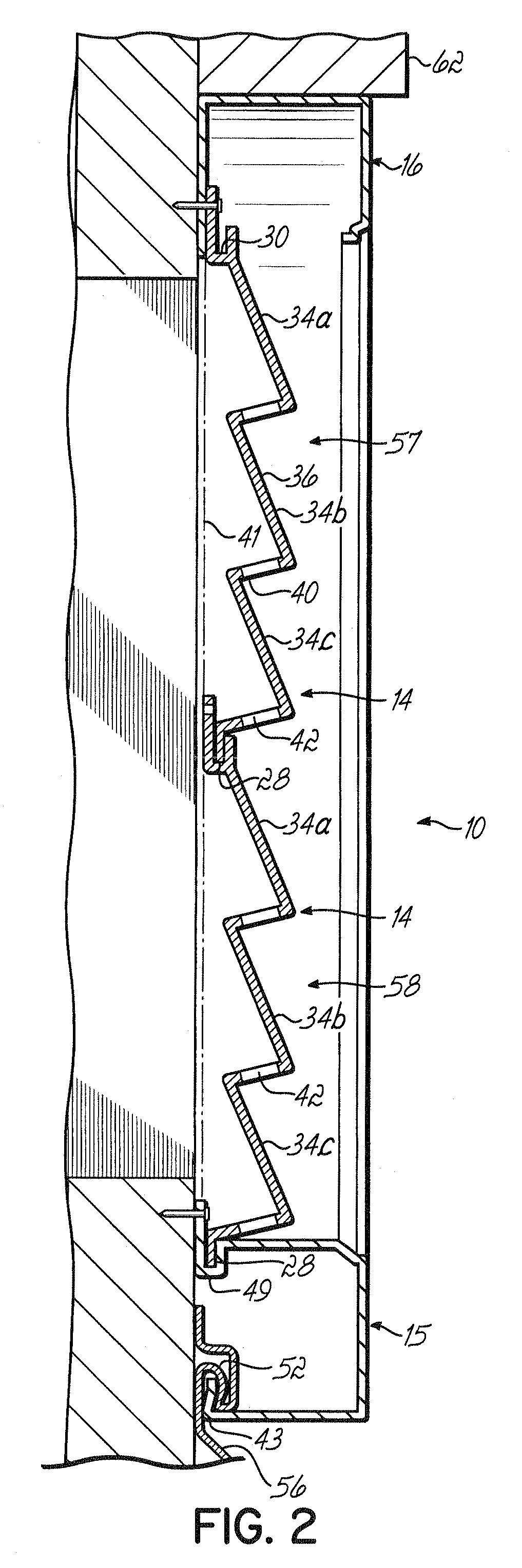
[0017]As shown in the Figures, a gable vent 10 is affixed to a building wall 12. The gable vent 10 includes slatted panels 14 surrounded by a lower trim section 15, as well as either sections of J channel 16 or, in certain cases, T channel 18.

[0018]The slatted panels 14 which can be formed by injection molding, include an upper edge 26 and a lower edge 28. The upper edge 26 includes an upper nail flange 30 and a channel 32 that is coplanar with the outer surface 33 of nail flange 30.

[0019]The slatted panels 14 include a plurality of slat members 34a, 34b, 34c. The slat members include an outwardly sloped portion 36 that leads to an inwardly extended portion 40 having a plurality of slots or vent openings 42. Portion 40 extends at least 90°, and preferably greater than 90°, relative to the back plane 41 of the panel, which allows the slots 42 to be formed by injection molding. The slots 42 are perpendicular to the direction of the slat members 34a, 34b and 34c.

[0020]The bottom edge ...


PUM


Abstract

A vent is formed from vent panels that can be formed by injection molding or vacuum forming. The vent panels include upper and lower edges. The upper edge includes a nailing flange and a channel. The channel is coplanar with the outer surface of a nailing flange. The lower edge is a linear flange adapted to fit within the channel of the next adjacent vent panel. The vent includes a lower trim member that has a flange and a channel coplanar with the upper surface of the flange and adapted to receive the bottom edge of a vent panel. The lower trim member is designed to attach to the upper edge of vinyl siding. J channels or T channels are used then to trim out the remaining portion of the vent. This allows one to form a custom vent by combining vent panels as desired.

Description

RELATED APPLICATION[0001]This application is related to and claims the benefit of U.S. Provisional Patent Application Ser. No. 60 / 869,465, filed on Dec. 11, 2006, the disclosure of which is incorporated herein by reference.BACKGROUND OF THE INVENTION[0002]Gable vents are used on the walls of buildings, generally below the pinnacle of the roofline. There are many types of gable vents formed from various materials, such as metal, wood, and plastic. There are also a variety of different shapes and sizes of gable vents. Many of these are specifically designed for use with vinyl siding. Such structures are disclosed, for example, in U.S. Pat. Nos. 6,076,321 and 5,673,526.[0003]Vents are generally assembled in a factory. A nonstandard-sized vent generally must be specially ordered. Specially ordered vents are very expensive. It also takes extra time to order and receive these. This can slow down a remodeling project.[0004]Pending U.S. application Ser. No. 11 / 381,762, entitled, “Component ...

Claims


Application Information

Patent Timeline
Patent Type & Authority Applications(United States)
IPC IPC(8): E06B7/082
CPCE06B7/082
Inventor VAGEDES, MICHAEL
Owner BLUEGRASS PRODS
Why Eureka
Try Eureka