
Apparatus and method for handling particulate material

a technology of particulate material and apparatus, which is applied in the direction of movable measuring chambers, instruments, packaged goods, etc., can solve the problems of difficult operation and cleaning, large space occupation, and high cost, and achieve the effect of reducing the weight of the load cell, fast and automatic monitoring

Inactive Publication Date: 2008-06-12
RHEE KYU R +1
View PDF22 Cites 8 Cited by
  • Summary
  • Abstract
  • Description
  • Claims
  • Application Information

AI Technical Summary

Benefits of technology

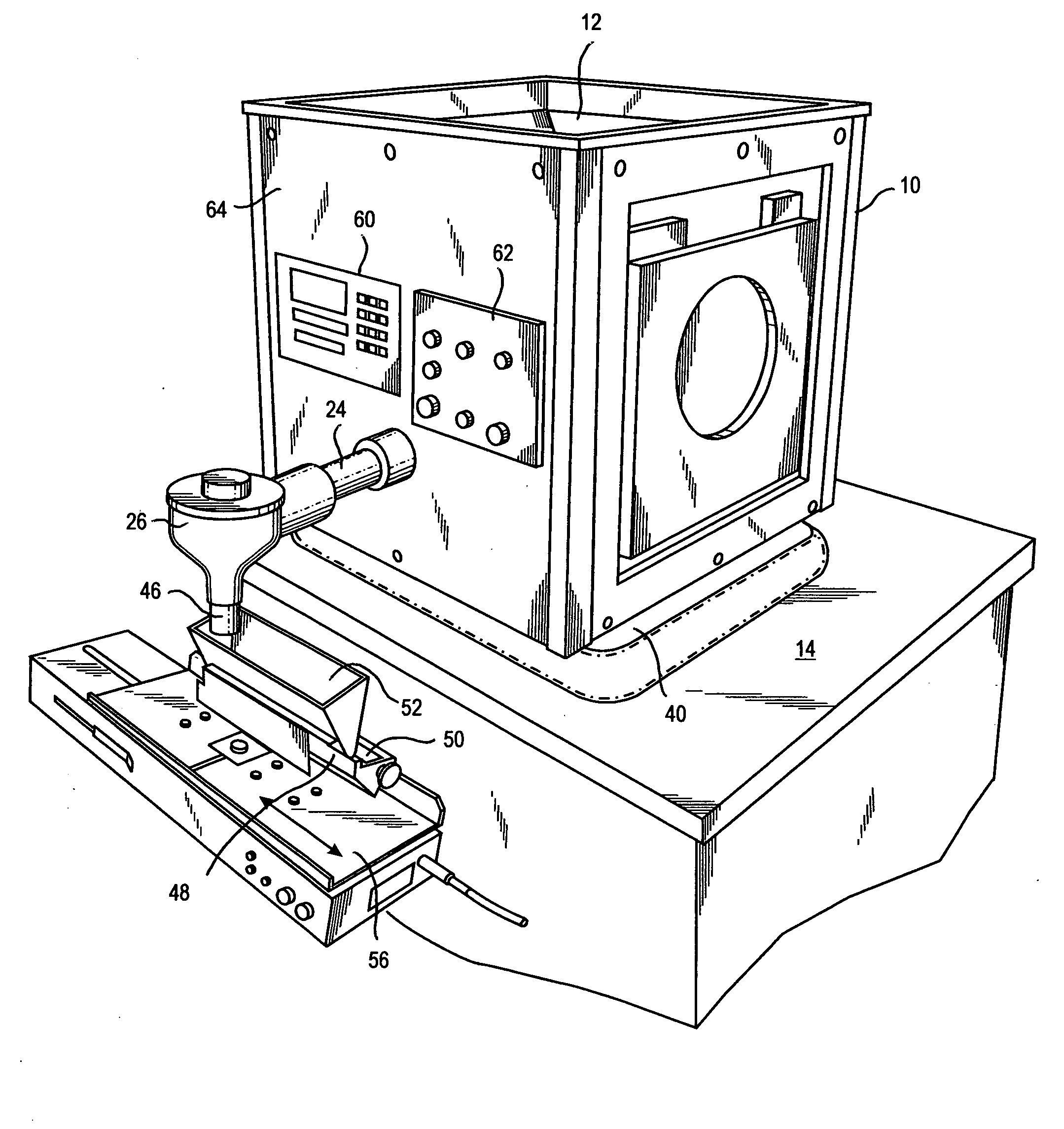
[0006]The container may be a bottle, a bag, a box or a toner cartridge, for example. A toner cartridge includes an elongated inlet on its top. The toner cartridge is preferably supported on a carriage for movement back and forth below the discharge spout, lengthwise of the inlet. The apparatus may include a load cell for monitoring the weight of the particulate material leaving the hopper. The hopper may be within an outer housing that sits down on the load cell. The weight on the load cell decreases in response to particulate material leaving the hopper. In this manner, the amount of particulate material delivered into a container can be quickly and automatically monitored.

Problems solved by technology

A problem with the prior art devices for handling and feeding toner is that they take up substantial space, are costly, and are relatively difficult to operate and clean.

Method used


Image

  • Apparatus and method for handling particulate material
  • Apparatus and method for handling particulate material
  • Apparatus and method for handling particulate material

Examples


Embodiment Construction

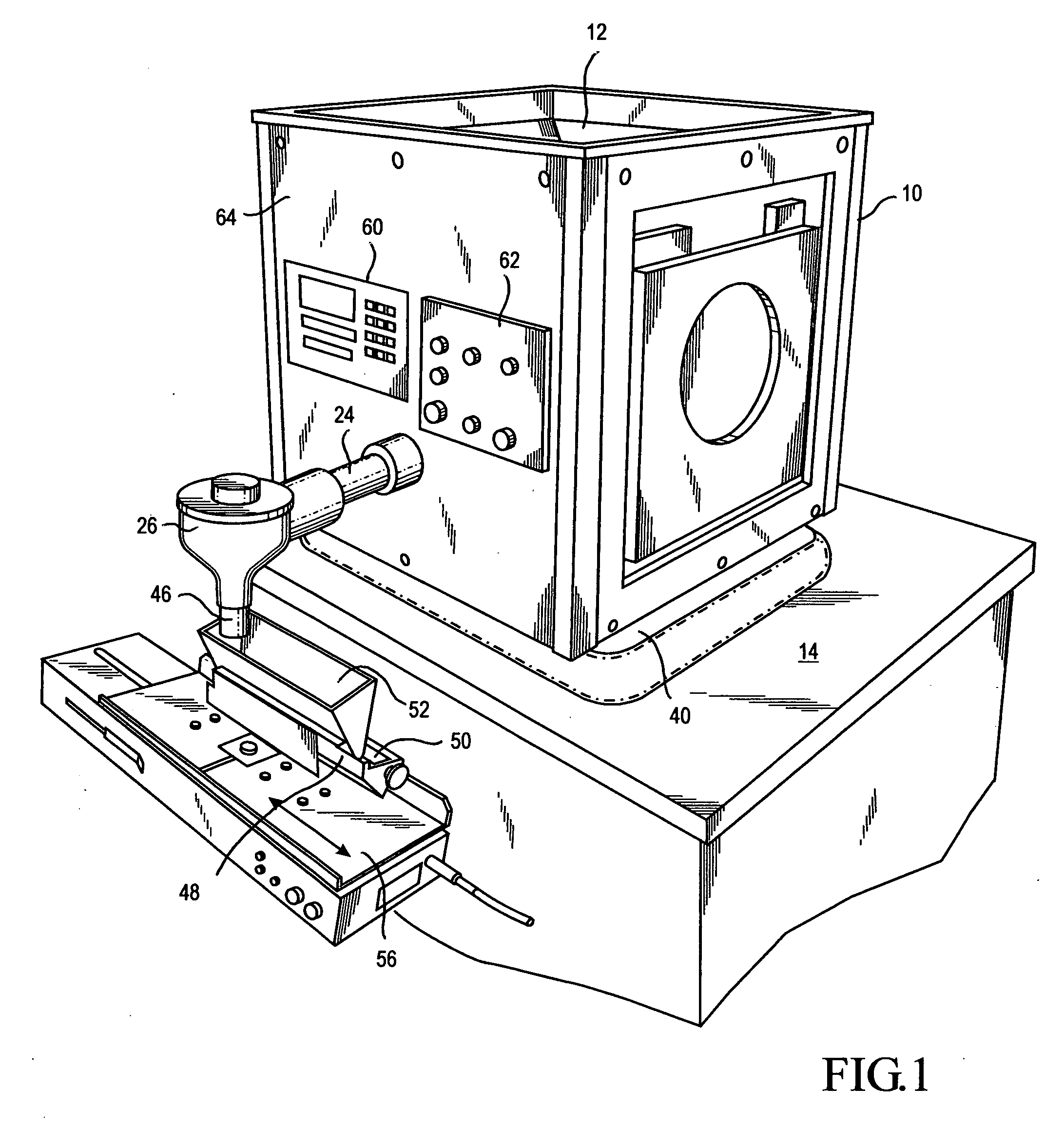
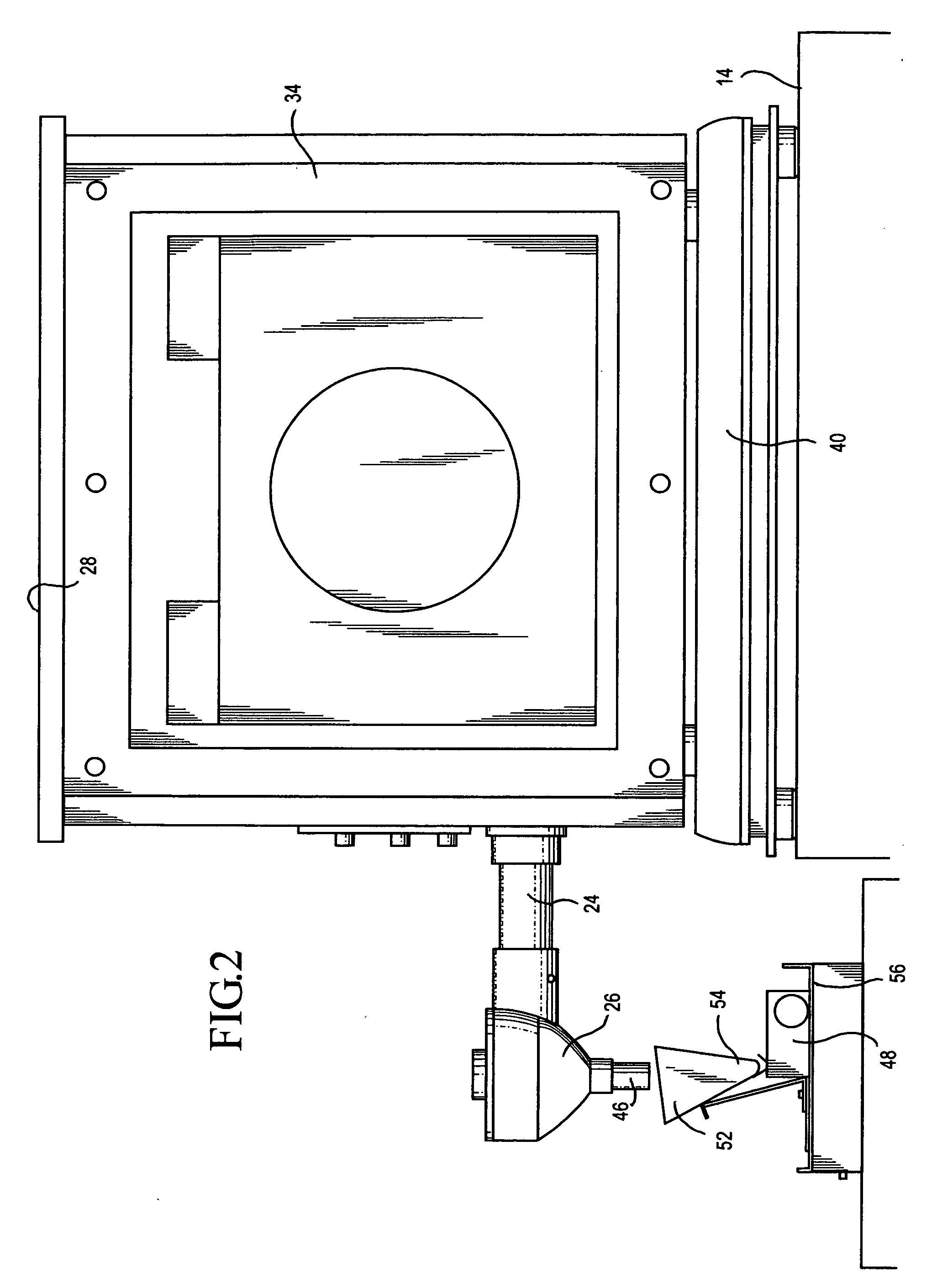
[0016]Referring to FIGS. 1-3, the illustrated embodiment of the invention comprises an outer housing 10, a hopper 12 within the housing 10 and a supporting structure 14 shown in the form of a countertop. The hopper 12 has an upper end 16, a lower end 18 and a downwardly tapering sidewall 20. A trough 22 is provided at the lower end 18. A discharge passageway 24 extends endwise outwardly from one end of the trough 22 to a downwardly opening outlet spout 26 that is outside of the housing 10. As shown by FIG. 3, the sidewalls of the hopper 12 converge as they extend downwardly. Hopper 12 is connected to the housing 10 at any suitable manner. Preferably, a lid 28 is provided for the housing 10 and the hopper 12. In FIG. 1, the lid 28 is removed. In FIG. 3, the lid 28 is installed.

[0017]An elongated helical feed screw 26 is positioned in the trough 22. One end of the feed screw 26 extends through the outlet passageway 24 over to where the outlet passageway 24 connects to the discharge sp...


PUM

PropertyMeasurementUnit
weightaaaaaaaaaa
plasticaaaaaaaaaa
speedaaaaaaaaaa

Abstract

Particulate material, such as toner, is stored within a hopper (12) which leads to a feed screw (30). The feed screw (30) moves the particulate material through an outlet passageway (24) into a discharge spout (26). The outlet (46) of the discharge spout (26) delivers the toner into the inlet of a funnel (52). The funnel (52) delivers the toner into the inlet (50) of a toner cartridge (48). The toner cartridge (48) and funnel (52) are mounted by a carriage (56) for back and forth movement below the outlet (46). The rate of toner feed is coordinated with the cartridge travel so that the toner is substantially evenly distributed into the cartridge (48).

Description

TECHNICAL FIELD[0001]This invention relates to an apparatus and method for storing and conveying finely divided particulate material such as, for example, toner that is used in laser printers, copying machines, and the like. More particularly, it relates to the provision of an apparatus and method for filling bottles, cartridges, and other containers, with toner, etc., in a fast, easy and economical way.BACKGROUND OF THE INVENTION[0002]Prior art devices and methods for dispensing toner and other finely divided particulate material are disclosed in the following U.S. Pat. No. 3,664,385, granted May 23, 1972, to Clarence F. Carter; U.S. Pat. No. 4,305,529, granted Dec. 15, 1981, to Charles W. Spehrley Jr.; U.S. Pat. No. 4,611,921, granted Sep. 16, 1986, to Jiterdna A. Patel; U.S. Pat. No. 6,000,446, granted Dec. 14, 1999, to Paul M. Wegman, Mikhail Vaynshteyn and Charles J. Balistere; and U.S. Pat. No. 6,722,406, granted Apr. 20, 2004, to Paul M. Wegman and Mikhail Vaynshteyn. The con...

Claims


Application Information

Patent Timeline
Patent Type & Authority Applications(United States)
IPC IPC(8): B65B3/26
CPCB65B1/06G03G15/0822B65B1/12
Inventor RHEE, KYU R.PARK, YOUNG DAE
Owner RHEE KYU R
Learn More