Device and method for continuously removing dissolved oxygen in fuel oil

A technology for dissolved oxygen and fuel oil, which is applied in separation methods, chemical instruments and methods, and treatment of hydrocarbon oil, etc. It can solve the problems of insufficient contact area, difficulty, foam generation, etc., and achieve the effect of increasing the contact surface area

Active Publication Date: 2018-09-14
TIANJIN UNIV
View PDF9 Cites 2 Cited by
  • Summary
  • Abstract
  • Description
  • Claims
  • Application Information

AI Technical Summary

Problems solved by technology

However, these methods for removing dissolved oxygen in fuel oil have the following problems: on the one hand, the contact area between nitrogen and fuel oil is not sufficient. In order to ensure the effect of dissolved oxygen removal, multi-stage separation is often used, which increases the weight of the equipment; on the other hand, due to The contact between nitrogen and fuel oil will cause foaming, and the subsequent oil and gas separation equipment will increase the weight of the equipment, and the poor subsequent separation effect will make the nitrogen carry more oil
At present, there is no report on the use of high-gravity technology and devices to remove dissolved oxygen in fuel oil, and the fuel oil system is fundamentally different from the water system. The value of saturated dissolved oxygen in fuel oil is much higher than that in water. The value is usually dozens or even hundreds of times of the saturated dissolved oxygen value in water. The technology used to remove dissolved oxygen in water cannot effectively remove dissolved oxygen in fuel oil, so fuel deoxygenation is more difficult than water deoxygenation

Method used


Image

  • Device and method for continuously removing dissolved oxygen in fuel oil
  • Device and method for continuously removing dissolved oxygen in fuel oil

Examples


Embodiment 1

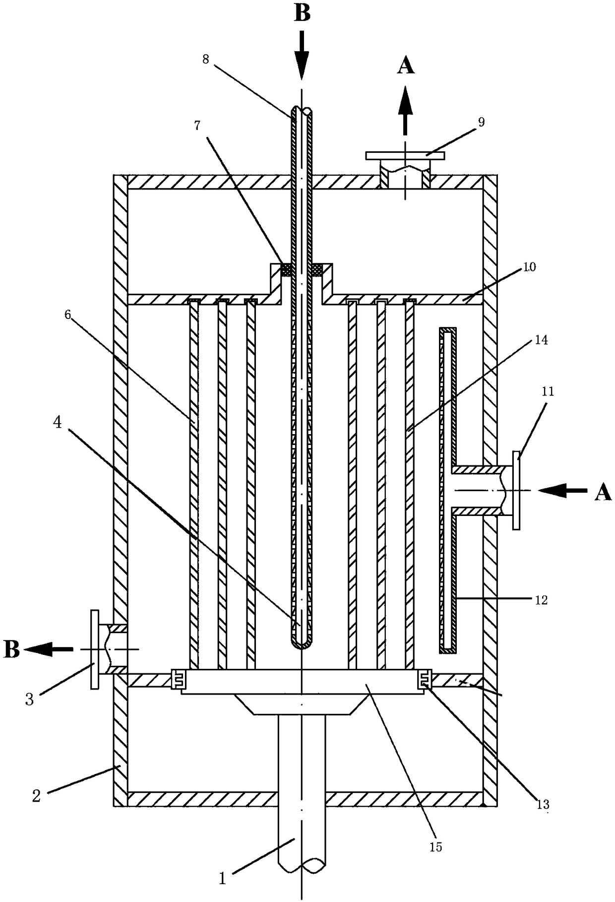
[0051] Embodiment 1: using the device of the present invention, the device has no static ring gap cylinder, and the moving ring gap cylinder is arranged concentrically in 3, such as figure 1 shown. The flow rate of aviation kerosene RP-3 is 1ml / s, the thickness of lipophilic dispersed packing is 100mm, the inlet oil temperature is room temperature, and the oxygen content is 70ppm; the rotating shaft speed is 500r / min, the system gauge pressure is 0.1MPa, and the nitrogen ventilation rate is 100ml / s, ventilation time is 15min. Results: The oxygen content of aviation kerosene RP-3 at the drain was 8ppb.

Embodiment 2

[0052] Embodiment 2: The conditions are the same as in Embodiment 1, and the oxygen-free gas is carbon dioxide gas. Results: The oxygen content of aviation kerosene RP-3 at the drain was 7ppb.

Embodiment 3

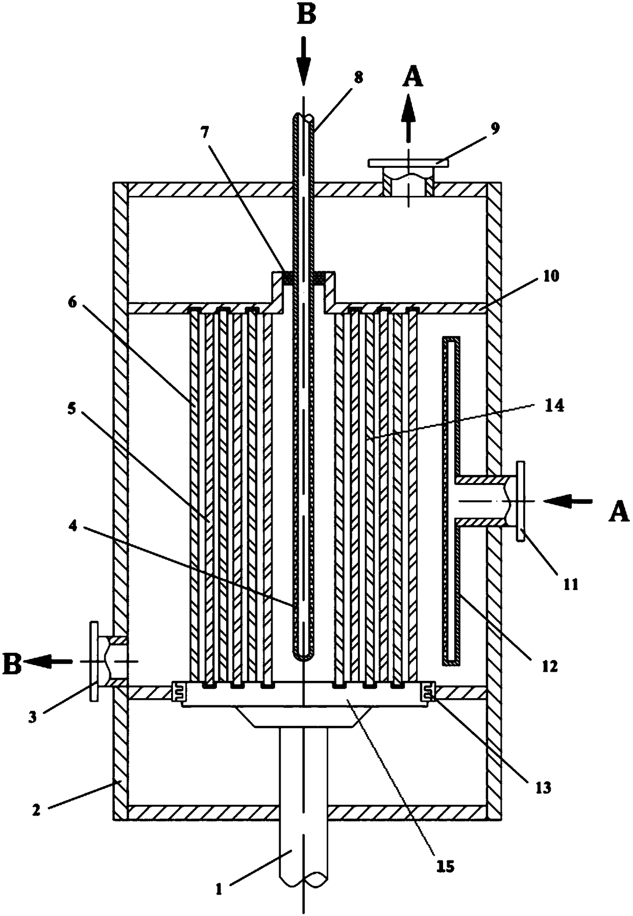
[0053] Embodiment 3: using the device of the present invention, the device has a static ring gap cylinder, each of which is 3 static ring gap cylinders and dynamic ring gap cylinders, arranged concentrically and alternately, as figure 2 shown. The flow rate of aviation kerosene RP-3 is 1ml / s, the thickness of lipophilic dispersed packing is 100mm, the inlet oil temperature is room temperature, and the oxygen content is 70ppm; the rotating shaft speed is 500r / min, the system gauge pressure is 0.1MPa, and the nitrogen ventilation rate is 100ml / s, ventilation time is 5min. Results: The oxygen content of aviation kerosene RP-3 at the drain was 8ppb.


PUM

PropertyMeasurementUnit
thicknessaaaaaaaaaa

Abstract

The invention discloses a device for continuously removing dissolved oxygen in fuel oil. The device comprises an outer shell (2), a liquid inlet (8), a liquid outlet (3), a gas inlet (11), an exhaustport (9), a rotating shaft (1), a disc (15) and a liquid redistribution pipe (4). A plurality of moving annulus barrels (6) with holes in side walls are axially and fixedly arranged on the upper end face of the disc (15) and filled with lipophilic dispersion filler (14). The invention further discloses a method for continuously removing dissolved oxygen in fuel oil by use of the device. The devicefor continuously removing dissolved oxygen in fuel oil has advantages of high continuity, low treatment cost and great removal effects, and the dissolved oxygen in fuel oil at the room temperature can be removed to 10ppb or below.

Description

technical field [0001] The invention belongs to the technical field of petrochemical equipment, in particular to a device for continuously removing dissolved oxygen from fuel oil. Background technique [0002] The dissolved oxygen in the fuel is the main reactant of the thermal oxidation reaction. When the temperature of the fuel oil itself reaches 420K, the dissolved oxygen in the fuel will undergo a thermal oxidation reaction with the hydrocarbons (especially aromatic compounds) in the oil until the dissolved oxygen Exhausted (420-650K), the process forms a large amount of thermal oxidation deposits or coke. In the field of aerospace, when aviation kerosene exchanges heat with cooling air in the heat exchanger, the thermal oxidation process gradually deepens as the temperature rises, and the thermal oxidation deposits generated at this time will be deposited on the inner wall of the heat exchanger, resulting in The heat transfer resistance of the radiator increases, which...

Claims


Application Information

Patent Timeline
Patent Type & Authority Applications(China)
IPC IPC(8): C10G31/00B01D19/00B01D19/02
CPCB01D19/0005B01D19/0026B01D19/02C10G31/00C10G2300/202
Inventor 刘国柱刘志强王涖王庆法张香文
Owner TIANJIN UNIV
Why Eureka
Try Eureka