
Motor mechanism of DC inverter-fed compressor

a technology of inverter-fed compressor and motor mechanism, which is applied in the direction of magnetic circuit rotating parts, piston pumps, magnetic circuit shapes/forms/construction, etc., can solve the problems of increasing processing work and assembly costs, reducing the number of components, and allowing small, thin and light-weight designs that tend to be more competitiv

Active Publication Date: 2008-06-12
IND TECH RES INST
View PDF7 Cites 18 Cited by
  • Summary
  • Abstract
  • Description
  • Claims
  • Application Information

AI Technical Summary

Benefits of technology

[0008]The object of the present invention is to provide a motor mechanism of DC inverter-fed compressor, which can effectively reduce the height of compressor, lower the costs of parts and assembly, render the compressor smaller, lighter and thinner, and at the same time, enhance the motor performance.

Problems solved by technology

The approach described above poses two problems.
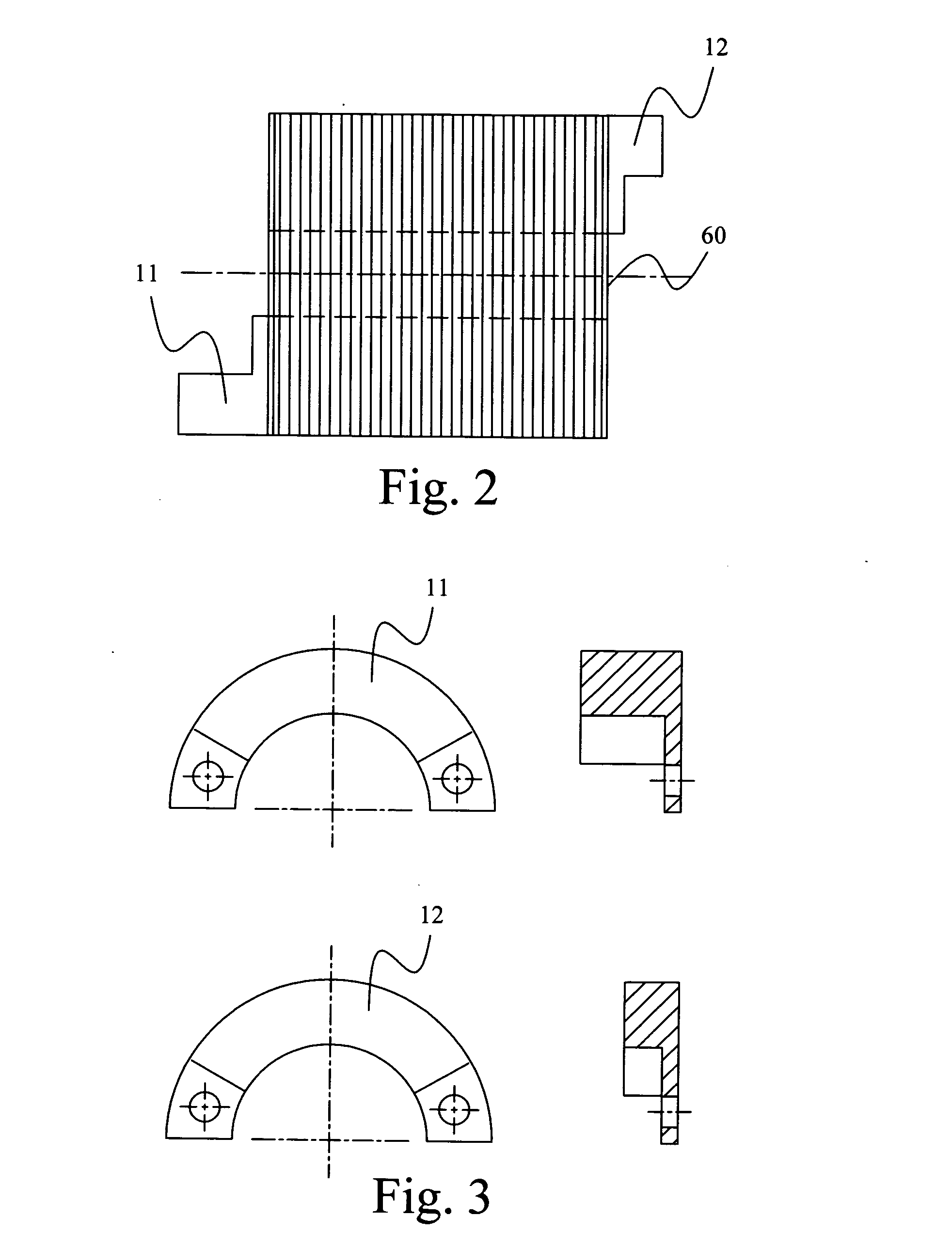
One is the arrangement of balance weights increase the height of compressor, which means the compressor will take more space in order to hold its components, thereby disallowing small, thin and light-weight design that tends to be more competitive on the market.
The other problem is that the upper and lower balance weights and their attachment to each side of motor rotor are structurally complex and add to the processing work and assembly costs.

Method used


Image

  • Motor mechanism of DC inverter-fed compressor
  • Motor mechanism of DC inverter-fed compressor
  • Motor mechanism of DC inverter-fed compressor

Examples


Embodiment Construction

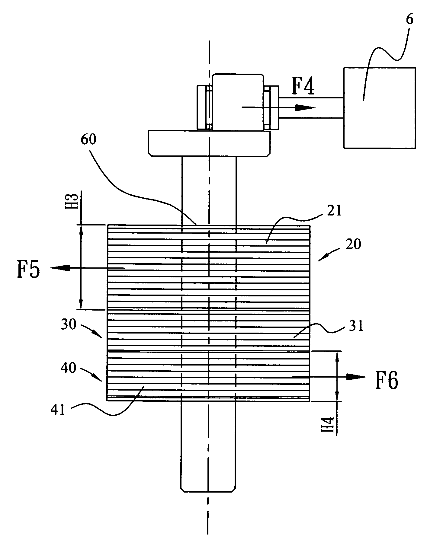
[0021]The present invention provides a motor mechanism of DC inverter-fed compressor. Referring to FIGS. 5A, 5B, 5C and 6, which are respectively a front view of the first, second, and third rotor units and a side view of the motor mechanism of DC inverter-fed compressor according to a first embodiment of the invention, the motor mechanism of DC inverter-fed compressor comprises a first rotor layer 20, a second rotor layer 30, a third rotor layer 40, and a shaft hole 60. The first rotor layer 20 is made up of a plurality of first rotor units 21 stacked together, and at least one magnet slot 50 able to hold a permanent magnet is provided at every quarter surface area of the first rotor units 21. The quantity and shape of magnet slot 50 may vary depending on design needs; the magnet slot 50 can be longitudinal or polygonal in shape. A plurality of first holes 22 are provided at one of the quarter areas of first rotor unit 21. The second rotor layer 30 is made up of a plurality of seco...


PUM


Abstract

A motor mechanism of DC inverter-fed compressor is disclosed, wherein a motor rotor includes a first rotor layer, a second rotor layer and a third rotor layer, made up respectively of a plurality of rotor units stacked together. The rotor units have a shaft hole in the middle and have at least one magnet slot that install a permanent magnet at every quarter surface area of the rotor units. The rotor units of the first rotor layer have a plurality of first holes at one of the quarter areas thereon, and the rotor units of the third rotor layer have a plurality of third holes, which are set up at an area opposing the first holes. The present invention can reduce the height of the compressor, the costs of parts and assembly, and increase the total efficiency of the motor and the compressor.

Description

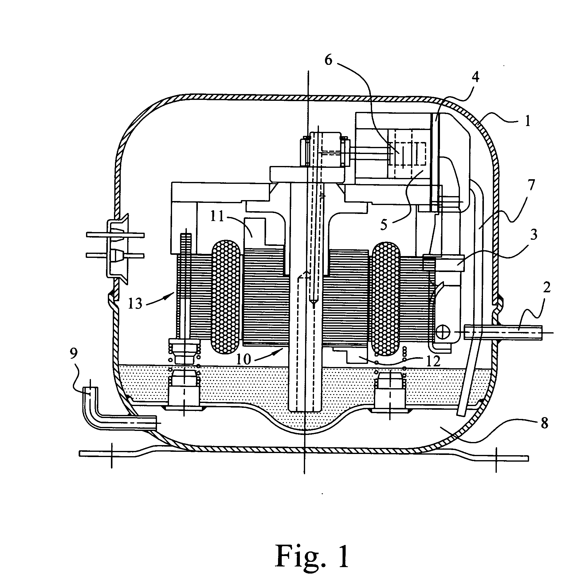
BACKGROUND OF THE INVENTION[0001]1. Field of the Invention[0002]The present invention relates to a motor mechanism, more particularly a motor mechanism of DC inverter-fed compressor that effectively reduces the height of compressor, cuts the costs of parts and assembly, and improves the overall performance of motor and compressor.[0003]2. Description of the Related Art[0004]The DC inverter-fed reciprocating compressor for refrigeration and air conditioning systems as shown in FIG. 1 works as follows: low pressure / temperature refrigerant gas enters the suction inlet 2 on the housing 1 into the intake chamber 3, reaches inside the cylinder 5 via the suction passage of valve seat 4, and undergoes compression by the pistons 6, where the refrigerant is compressed into high pressure / temperature gas, which then enters the discharge chamber 8 via the pipes 7 and is discharged outside the compressor via the refrigerant outlet 9.[0005]The motor stator 13 is fixed inside the compressor, while ...

Claims


Application Information

Patent Timeline
IPC IPC(8): H02K16/00H02K1/27
CPCF04B35/04H02K7/04H02K1/2766
Inventor HSIAO, TSE-LIANGYU, PEI-YU
Owner IND TECH RES INST
Learn More