Display device

a display device and display technology, applied in non-linear optics, instruments, optics, etc., can solve the problems of inability to express perfect black, and disadvantageous narrow expressible tonal range of brightness, so as to improve the use efficiency of light emitted from the light quantity control device, the effect of good display properties

Active Publication Date: 2008-06-12
E INK CORPORATION
View PDF4 Cites 10 Cited by
  • Summary
  • Abstract
  • Description
  • Claims
  • Application Information

AI Technical Summary

Benefits of technology

[0007]An advantage of the present invention is to provide a new type of color display device exhibiting good display properties.
[0008]According to an aspect of the invention, a display device includes a color filter having a multiple types of electrochromic dyes disposed on a pixel by pixel basis, the electrochromic dyes allowing reversible coloring or decoloring, and a light quantity control element for controlling an amount of light emitted to each of the electrochromic dyes of the color filter.
[0009]In this manner, formation of the light quantity control element for controlling the quantity of light emitted to the color filter having the electrochromic dyes enables display of a desired color by mixing the multiple types of electrochromic dyes as well as control of brightness of the light.
[0010]In this case, the color filter may have the multiple types of electrochromic dyes arranged in, a plane correspondingly to a single pixel, resulting in a color display device being achieved. All of the electrochromic dyes inside the single pixel are made colorless by being decolorized such that the light emitted from a side of the light quantity control element is not absorbed and white display is realized. Therefore, the color filter enables display of brighter white compared with the known color filter with RGB (red, green, blue) sub-pixels.
[0011]It is more preferable that the color filter have the multiple types of electrochromic dyes disposed in a laminated manner correspondingly to a single pixel. For example, it is preferable that the three types of electrochromic dyes developing cyan, magenta, and yellow, respectively, be disposed in a laminated manner. Accordingly, the electrochromic dyes developing cyan, magenta, and yellow, respectively, can be laminated inside the single pixel without dividing the single pixel into RGB sub-pixels, for example. The electrochromic dyes other than those necessary for display of a desired color are made transparent and colorless, thereby not absorbing the light. Therefore, the use efficiency of the light emitted from the light quantity control device can be improved.
[0012]The color filter may further have two transparent electrodes opposing to each other in a manner to have the electrochromic dyes intervened therebetween. A voltage applied between the two electrodes makes it possible to control coloring and decoloring of the electrochromic dyes.

Problems solved by technology

The electrochromic device, however, disadvantageously has a narrow expressible tonal range of brightness.
Another problem is the inability to express a perfect black.

Method used


Image

  • Display device
  • Display device
  • Display device

Examples


first embodiment

[0027]Hereinafter, embodiments of the present invention will be described with reference to drawings.

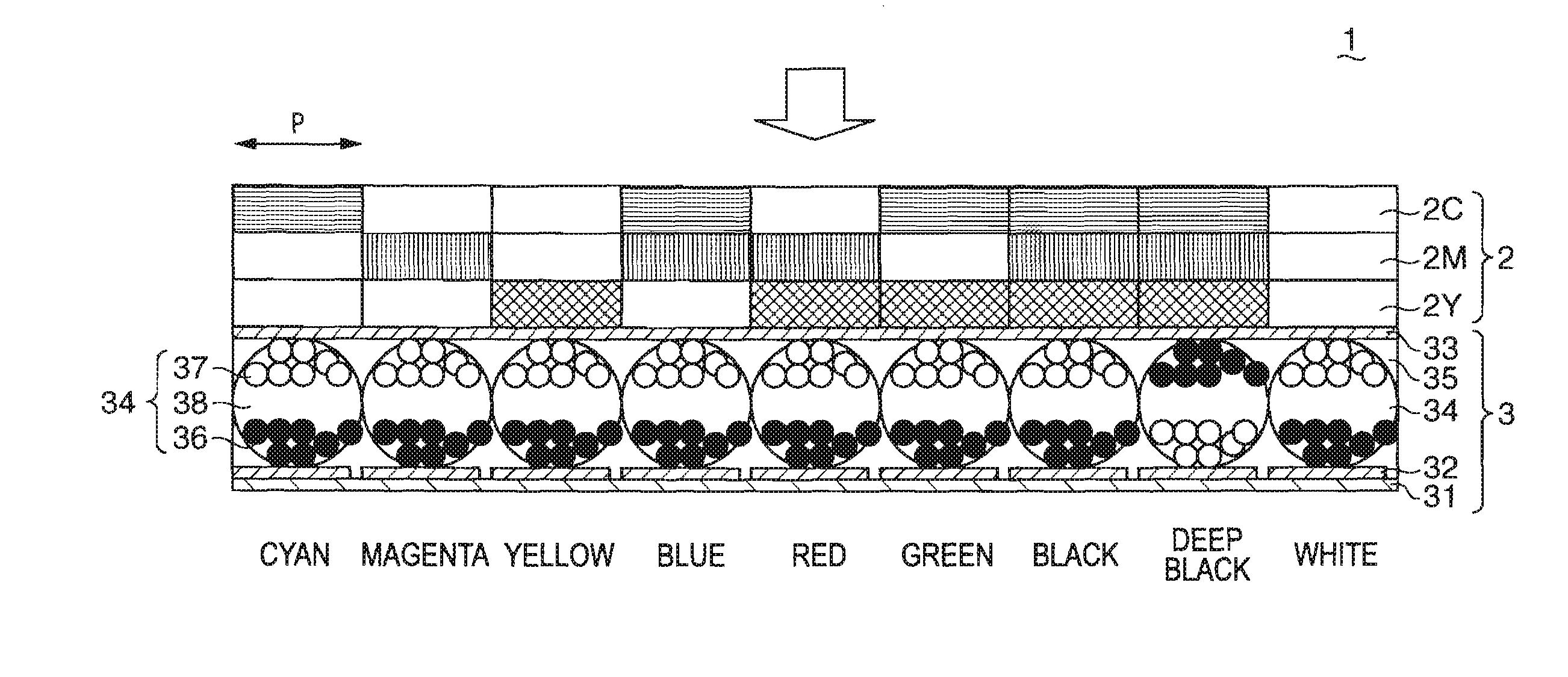
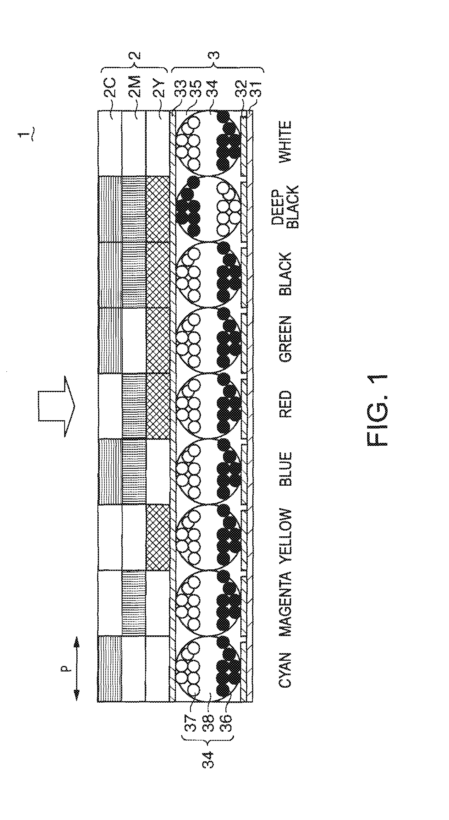
[0028]FIG. 1 is a cross-sectional view of a reflective display device according to a first embodiment.

[0029]As shown in FIG. 1, a display device 1 according to this embodiment is structured by laminating a color filter 2 and a light quantity control element 3.

[0030]The color filter 2 has a multiple types of layers of electrochromic (EC) dyes referred to as electrochromic layers. Each of the layers is disposed on a pixel P by pixel P basis and exhibits reversibly coloring or decoloring characteristics. In this embodiment, the single pixel P is provided therein with the electrochromic dye developing cyan, i.e., a cyan EC dye 2C, the electrochromic dye developing magenta, i.e., a magenta EC dye 2M, and the electrochromic dye developing yellow, i.e., a yellow EC dye 2Y, which are placed in a laminated manner.

[0031]An electrochromic material exhibits reversible coloring or decoloring char...

second embodiment

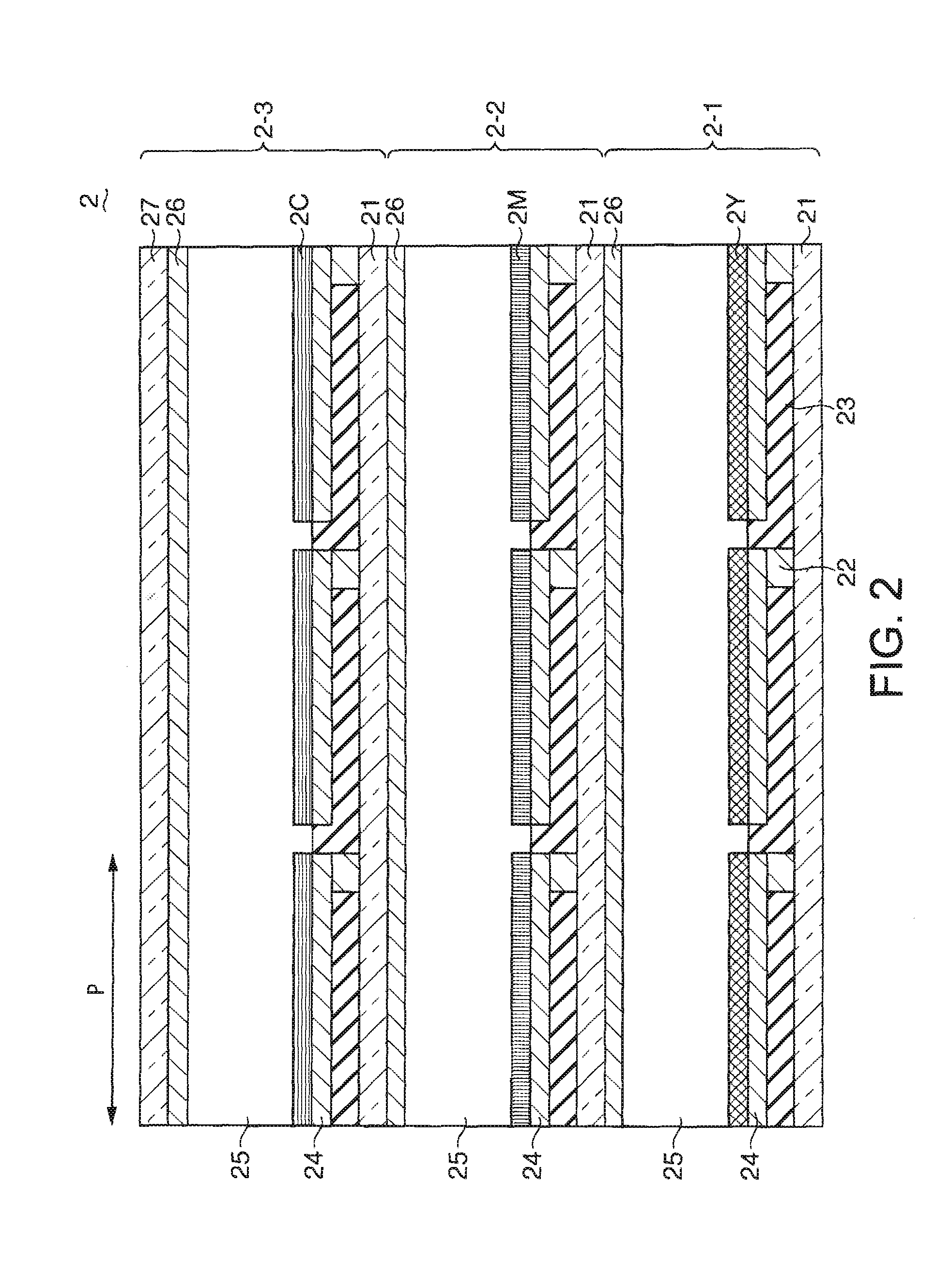
[0055]FIG. 3 is a schematic cross-sectional view of the color film 2 of a display device according to a second embodiment. Explained in the second embodiment is a case where the laminated body of the EC dyes 2C, 2M, and 2Y is intervened between the display electrode 24 and the counter electrode 26.

[0056]The color filter 2 has the transparent substrate 21 made of glass or the like, the thin-film transistor 22 and the interlayer film 23 both formed on the transparent substrate 21, the display electrode 24 formed on the thin-film transistor 22 and the interlayer film 23, the EC dyes 2C, 2M, and 2Y, the counter electrode 26 disposed on the laminated body of the EC dyes with the electrolyte intervened, and a counter electrode 27 made of grass or the like formed on the counter electrode 26. The counter electrode 24 is common to all pixels and the display electrode 24 is divided on a pixel basis.

[0057]The second embodiment requires selection of the EC dyes 2C, 2M, and 2Y that satisfy a fol...

third embodiment

[0061]FIG. 4 is a view showing a structure of a display device 1 according to a third embodiment. Examples of the reflective display device are explained in the first and second embodiments but an example of a transmissive display device is explained in this embodiment.

[0062]In this embodiment, the display device is formed by laminating the color filter 2, the light quantity control element 3, and a backlight 4 serving as a light source. A structure of the color filter 2 is the same as that of the first embodiment, so that corresponding explanation is omitted. The backlight 4 emits write light to the light quantity control element 3.

[0063]The light quantity control element 3 controls the quantity of light emitted to the laminated body of the EC dyes 2C, 2M, and 2Y. In this embodiment, the light quantity control element 3 controls the quantity of transmitted light which is emitted from the backlight 4. Therefore, in this embodiment, a liquid crystal 39 is used as a display medium fil...


PUM

PropertyMeasurementUnit
voltageaaaaaaaaaa
electrochromicaaaaaaaaaa
transparentaaaaaaaaaa

Abstract

A display device including a color filter having a multiple types of electrochromic dyes disposed on a pixel by pixel basis, the electrochromic dyes allowing reversible coloring or decoloring, and a light quantity control element for controlling an amount of light emitted to the electrochromatic dyes of the color filter.

Description

[0001]The entire disclosure of Japanese Patent Application No. 2006-334726, filed Dec. 12, 2006 is expressly incorporated by reference herein.BACKGROUND[0002]1. Technical Field[0003]The present invention relates to a display device.[0004]2. Related Art[0005]Electrochromism is a phenomenon of reversible change in color resulting from electric-field oxidation or reduction reaction, which reversibly occurs upon application of a voltage. Such an electrochromic display device has been studied, that utilizes an electrochromic compound exhibiting coloring or / and decoloring characteristics that cause the aforementioned phenomenon. JP-A-2006-106669 is an example of related art.[0006]The electrochromic device, however, disadvantageously has a narrow expressible tonal range of brightness. Another problem is the inability to express a perfect black.SUMMARY[0007]An advantage of the present invention is to provide a new type of color display device exhibiting good display properties.[0008]Accordi...

Claims


Application Information

Patent Timeline
Patent Type & Authority Applications(United States)
IPC IPC(8): G02F1/153G02F1/167G02F1/16757
CPCG02F1/133514G02F1/13473G02F2201/44G02F1/167G02F1/157G02F1/16757
Inventor ABE, DAISUKE
Owner E INK CORPORATION
Why Eureka
Try Eureka