
Method for improving energy output of a nuclear reactor, method for determining natural uranium blanket layer for a fuel bundle, and a fuel bundle having a variable blanket layer

a technology of nuclear reactor and blanket layer, which is applied in the direction of nuclear elements, nuclear engineering problems, greenhouse gas reduction, etc., can solve the problems of reducing thermal margin, reducing thermal output, and 5% enriched uranium fuels

Active Publication Date: 2008-06-12
GLOBAL NUCLEAR FUEL -- AMERICAS
View PDF21 Cites 8 Cited by
  • Summary
  • Abstract
  • Description
  • Claims
  • Application Information

AI Technical Summary

Benefits of technology

[0029]An example embodiment of the present invention is directed to a method for improving the energy generating output of a nuclear reactor containing one or more fuel rods in one or more fuel rod bundles while satisfying a maximum subcritical banked withdrawal position (MSBWP) reactivity limit. In the method, enrichments of individual fuel rods in an axial cross-section of a lattice being evaluated at the top of the fuel bundle are ranked, and

Problems solved by technology

Although amounts greater than about 5% (by weight) of 235U in enriched uranium could be used, commercial power-producing nuclear reactors have traditionally been limited to 5% enriched uranium fuels.
Yet the larger 12-inch blanket at the top results in an effectively shorter fuel bundle, which can reduce thermal margins in non-peripheral portions of the core and hence lower thermal output.
Moreover, in addition to being able to satisfy limits for thermal parameters such as MFLPD (Maximum Fraction of Limiting Power Density), MAPRAT (the ratio of MAPLHGR or Maximum Average Planar Linear Heat Generation compared to its limit), MFLCPR (Maximum Fraction of Limiting Critical Power Ratio), and limits for reactivity parameters (cold shutdown margin (CSDM) and hot excess reactivity (HOTX)), use of the larger 12-inch blanket may complicate satisfying the limit or condition for the reactivity parameter known as the maximum subcritical banked withdrawal position (MSBWP).

Method used


Image

  • Method for improving energy output of a nuclear reactor, method for determining natural uranium blanket layer for a fuel bundle, and a fuel bundle having a variable blanket layer
  • Method for improving energy output of a nuclear reactor, method for determining natural uranium blanket layer for a fuel bundle, and a fuel bundle having a variable blanket layer
  • Method for improving energy output of a nuclear reactor, method for determining natural uranium blanket layer for a fuel bundle, and a fuel bundle having a variable blanket layer

Examples


Embodiment Construction

[0053]In an example embodiment to be described in detail hereafter, there is described a method of improving the energy generating output of a nuclear reactor while satisfying the MSBWP reactivity limit.

[0054]As will be seen below, certain example embodiments are directed to a method of identifying and / or enriching selected fuel rods in the 2nd top most six inches of nuclear reactor fuel bundles (e.g., between height=138 to 144 inches) with 235U which satisfies the MSBWP reactivity limit / constraint or safety condition. Other variations are possible within the scope of the present invention. For example, instead of 235U, another fissionable fuel may be used as appropriate. Other variations are also contemplated to be within the scope of the present invention as are recognized by those of ordinary skill in the art.

[0055]An aspect of the present invention relates to the design of fresh fuel bundles which satisfy the MSBWP reactivity limit criteria / safety condition and also improve the ...


PUM


Abstract

In a method for improving the energy generating output of a nuclear reactor containing one or more fuel rods in one or more fuel rod bundles while satisfying a maximum subcritical banked withdrawal position (MSBWP) reactivity limit, enrichments of individual fuel rods in an axial cross-section of a lattice being evaluated at the top of the fuel bundle are ranked, and the fuel pins of the highest ranked rod location in the lattice are replaced with natural uranium pins. A core simulation is then performed to determine whether there is any margin to a MSBWP reactivity limit. For each lower ranked candidate rod position, the pin replacing and core simulation functions are repeated until no rod location violates the MSBWP reactivity limit, so as to achieve a desired lattice design for the top of the fuel bundle.

Description

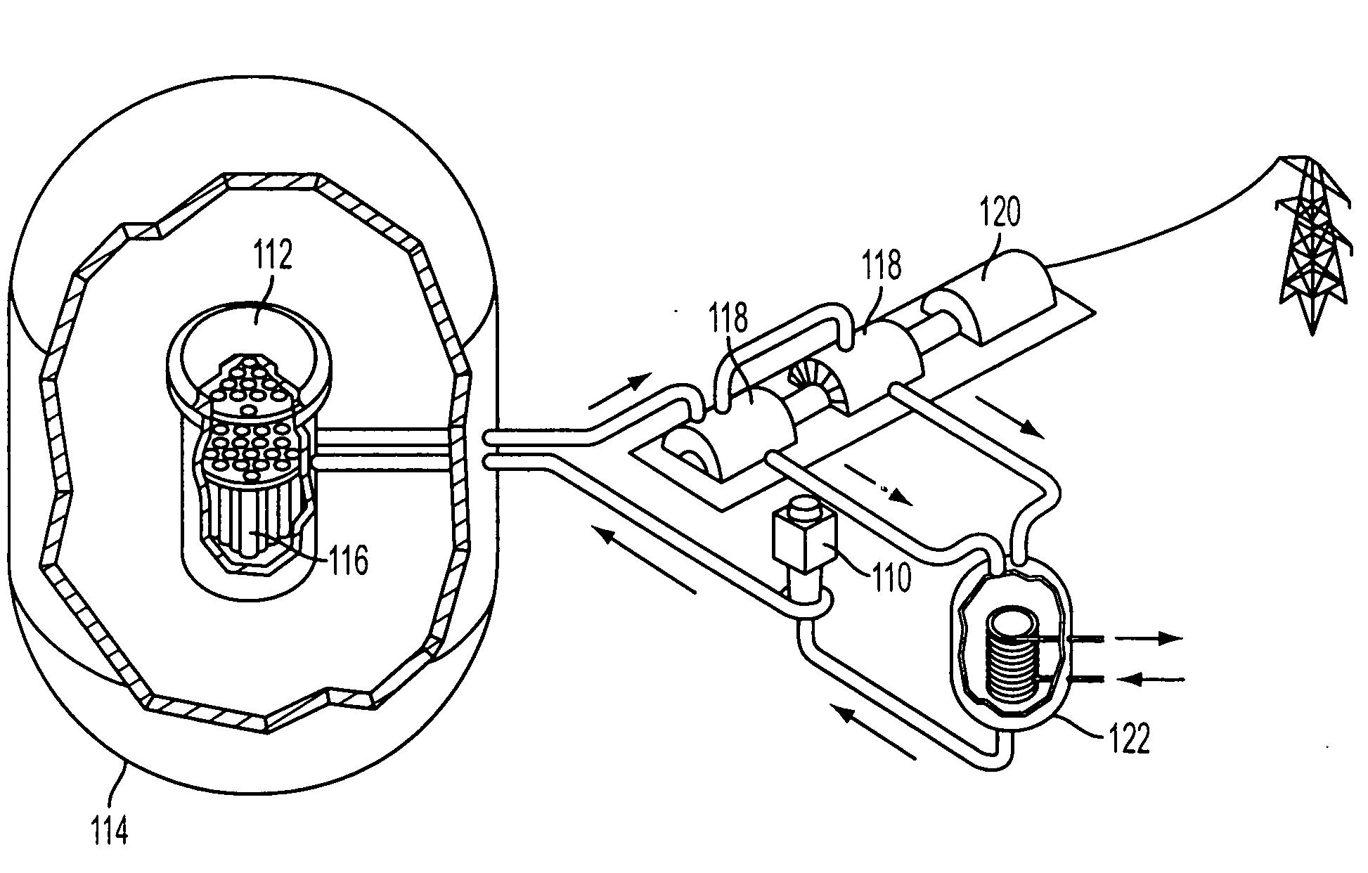
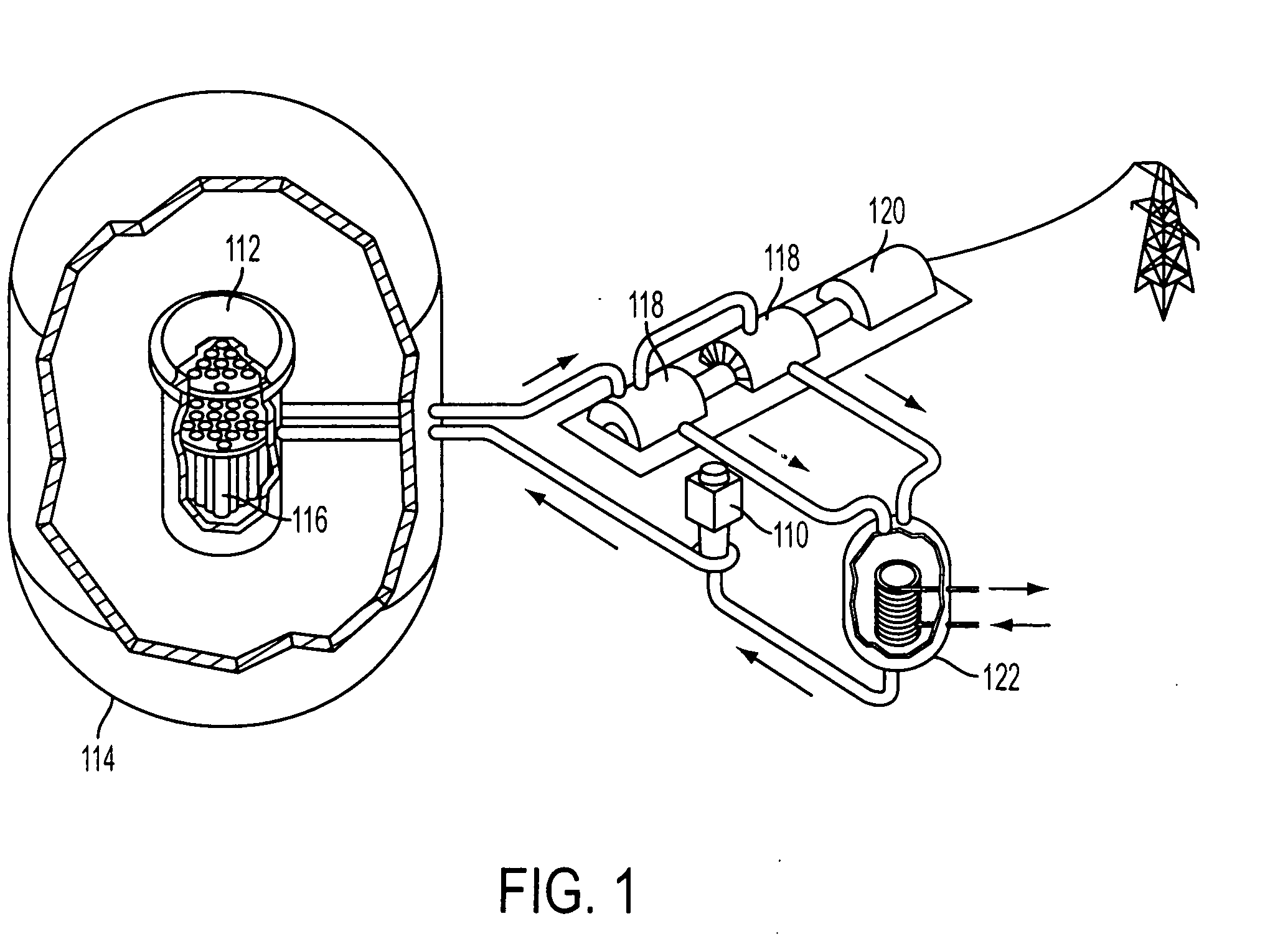
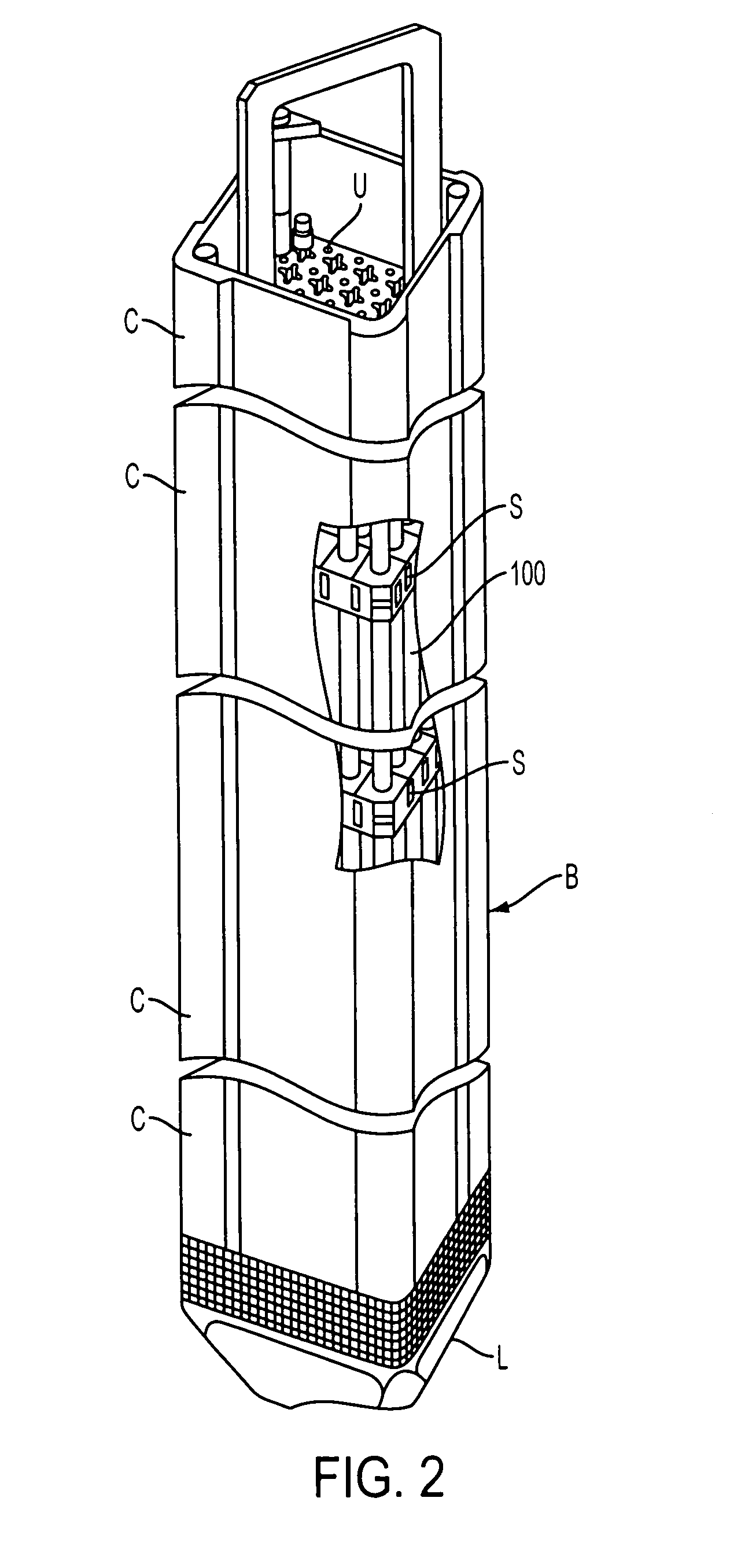
BACKGROUND OF THE INVENTION[0001]1. Field of the Invention[0002]Example embodiment(s) of the present invention are directed to methods of improving the energy output of a nuclear reactor, while satisfying a minimum subcritical bank withdrawal position (MSBWP) safety condition, to a method for determining fuel rods to be subject to an extended natural uranium blanket layer, so as to employ a variable natural blanket for selectable fuel rods in one or more fuel bundle(s) of the reactor, and to a fuel bundle which has a variable natural uranium blanket.[0003]2. Description of the Related Art[0004]FIG. 1 illustrates a conventional boiling water reactor (BWR); FIG. 2 illustrates a fuel bundle in the core of a reactor vessel; and FIG. 3 represents an x-y map distribution of a 10×10 array of fuel rods and water rods in a fuel bundle located in one quadrant of a control blade.[0005]As show in FIG. 1, a pump 110 supplies water via a conduit (e.g., in the direction of arrow from pump 110 towa...

Claims


Application Information

Patent Timeline
IPC IPC(8): G21C17/00
CPCG21C3/328G21C7/00G21D3/001Y02E30/39G21Y2002/304G21Y2004/30Y02E30/38G21Y2002/201Y02E30/30Y02E30/00
Inventor KROPACZEK, DAVID JOSEPHREA, JOHN PATRICKASGARI, MEHDI
Owner GLOBAL NUCLEAR FUEL -- AMERICAS
Learn More