
Fan device capable of increasing air pressure and air supply

a technology of which is applied in the direction of machines/engines, stators, liquid fuel engines, etc., can solve the problems of air pressure loss, inability to provide sufficient air supply for centrifugal fans, and difficult design of axial flow fans, etc., to and increase air pressure and air supply

Inactive Publication Date: 2008-06-12
CHANG BOR HAW +2
View PDF7 Cites 16 Cited by
  • Summary
  • Abstract
  • Description
  • Claims
  • Application Information

AI Technical Summary

Benefits of technology

[0006]Accordingly, an object of the present invention is to provide a fan device capable of increasing air pressure and air supply in which a flow guide part with a plurality sets of fan wheels in different sizes are provided to increase the air pressure and the air supply.
[0007]another object of the present invention is to provide a fan device capable of increasing air pressure and air supply with which system resistance to the fan device is capable of being overcome effectively.
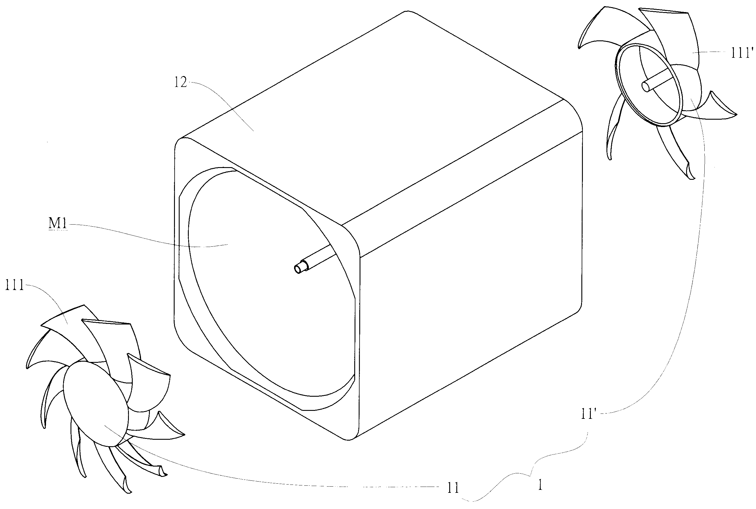
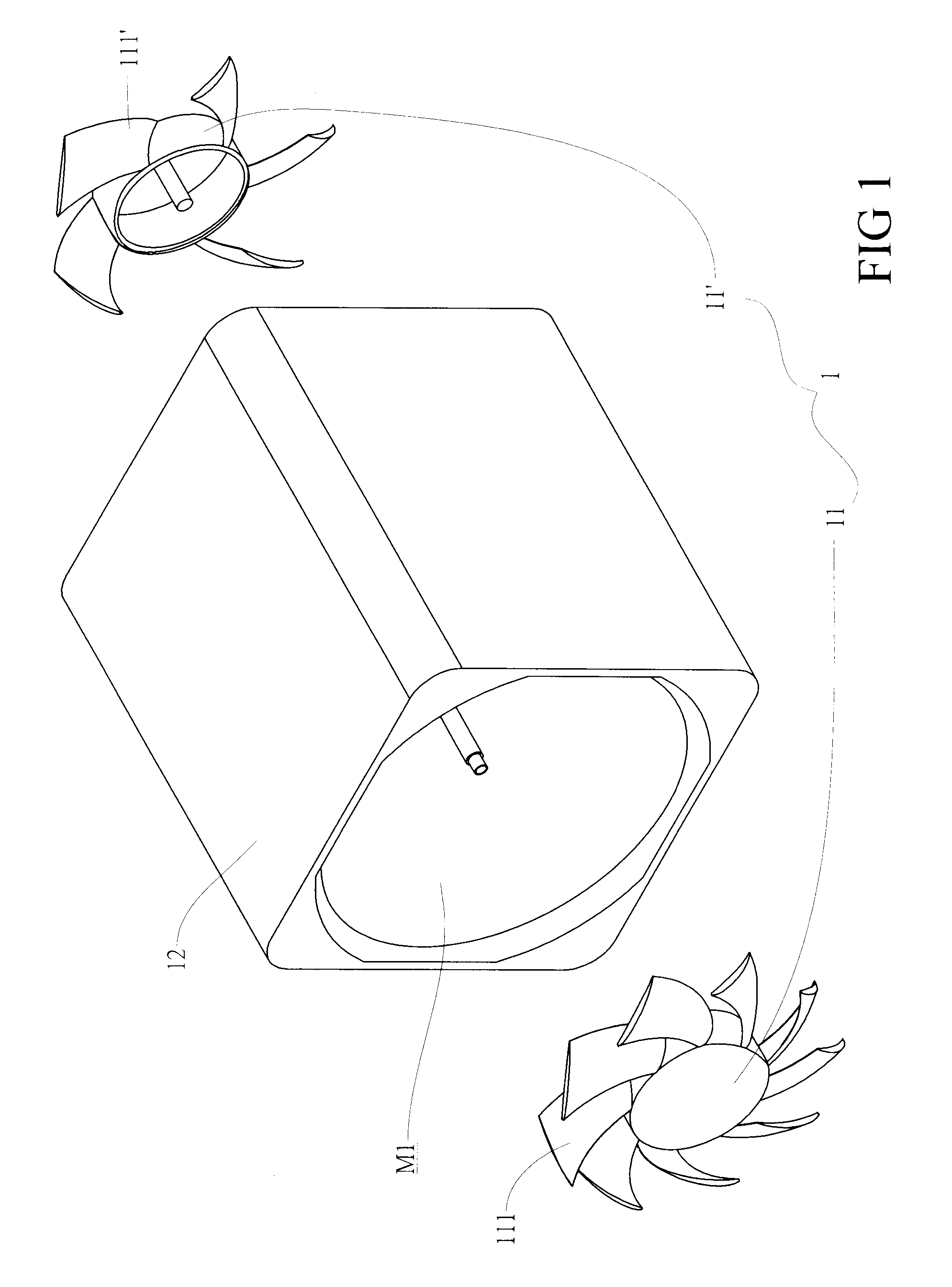
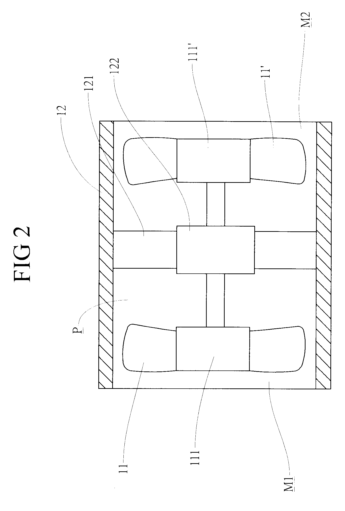
[0008]In order to achieve the preceding object, a fan device capable of increasing air pressure and air supply according to the present invention includes a frame, a first blade wheel, a second blade wheel and a guide flow part. The frame is a hollow casing to define a flow passage with a first air port and a second air port available for air passing through. The guide flow part is held with a support in the flow passage and a driving device is received in the support. The first blade wheel with first fan blades and the second blade wheel with second fan blades are disposed in the flow passage next to the support for being driven by the driving device. The number of the first fan blades is more than that of the second fan blades. Once the first and second fan wheels are in operation, air induced by the fan wheels is guided by the guide flow part and air pressure and air supply of the fan system are increased substantively due to number of the first fan blades being greater than that of the second fan blades.

Problems solved by technology

Normally, less Ns value means air resistance is greater, that is, the axial flow fan is hard to be designed to meet requirement of actual application and the centrifugal fan is incapable of offering sufficient air supply in spite of having sufficient air pressure.
It is found that the rib sections create the air resistance after a delicate analysis of the rib sections vs. air pressure being conducted.
Due to the fan rotating to perform work to the air, the air flow creates turbulence to constitute spiral air to result in air pressure loss and affect performance of the fan.

Method used


Image

  • Fan device capable of increasing air pressure and air supply
  • Fan device capable of increasing air pressure and air supply
  • Fan device capable of increasing air pressure and air supply

Examples


Embodiment Construction

[0023]Referring to FIGS. 1, and 2, the fan device capable of increasing air pressure and air supply according to the present invention includes a first blade wheel 11, a second blade wheel 11′ and a frame 12. The first blade wheel 11 and the second blade wheel 11′ each have a plurality of fan blades 111, 111′ being arranged radially. The frame 12 is a casing with a hollow space to define a flow passage P with a first air port M1 and a second air port M2 available for air passing through. The frame 12 provides a guide flow part 121, which is composed of a plurality of static blades, and a support 122 is joined to the guide flow part 121. The guide flow part 121 has a shape similar to the fan blades 111, 111′ respectively. The support 122 further receives a motor (not shown), which is the driving device of the first and second blade wheels 11, 11′, so that the fan blades 111, 111′ are capable of rotating and air flow induced by the fan blades 111, 111′ is guided with the guide flow pa...


PUM


Abstract

A fan device capable of increasing air pressure and air supply includes a frame, a first blade wheel, a second blade wheel and a guide flow part. The frame is a hollow casing to define a flow passage with a first air port and a second air port available for air passing through. The guide flow part is held with a support in the flow passage and a driving device is received in the support. The first blade wheel with first fan blades and the second blade wheel with second fan blades are disposed in the flow passage next to the support for being driven by the driving device. The number of the first fan blades is more than that of the second fan blades. Once the first and second fan wheels are in operation, air induced by the fan wheels is guided by the guide flow part and air pressure and air supply of the fan system are increased substantively due to number of the first fan blades being greater than that of the second fan blades.

Description

BACKGROUND OF THE INVENTION[0001]1. Field of the Invention[0002]The present invention is related to a fan device and particularly to a fan device capable of increasing air pressure and air supply.[0003]2. Brief Description of the Related Art[0004]Currently, there are three types of fans available on the market, the axial flow fan, the centrifugal fan and the transverse flow fan. The most popularly used one is the axial flow fan. Comparing the axial flow fan and the centrifugal fan with specific speed (Ns), the axial flow fan is suitable of being used in case of Ns>3 and the centrifugal fan is suitable for being used in case of Ns<1.5. Normally, less Ns value means air resistance is greater, that is, the axial flow fan is hard to be designed to meet requirement of actual application and the centrifugal fan is incapable of offering sufficient air supply in spite of having sufficient air pressure.[0005]The conventional cooling fan usually has a fan frame being supported with bar ...

Claims


Application Information

Patent Timeline
Patent Type & Authority Applications(United States)
IPC IPC(8): F04D19/02F04D29/52
CPCF04D29/325F04D19/007
Inventor CHANG, BOR-HAWLIU, WEN-HAOHUANG, CHIA-LIEH
Owner CHANG BOR HAW
Learn More