Magnetic levitation sliding structure

Inactive Publication Date: 2008-06-12
SAMSUNG TECHWIN CO LTD
View PDF2 Cites 113 Cited by
  • Summary
  • Abstract
  • Description
  • Claims
  • Application Information

AI Technical Summary

Benefits of technology

[0015]According to an aspect of the present invention, there is provided a magnetic levitation sliding structure comprising: a first slider member including a guide portion; a second slider member including a receiving portion that has a complementary shape to the guide portion and slidably mates therewith; a first magne

Problems solved by technology

Accordingly, it may be difficult for a user t

Method used


Image

  • Magnetic levitation sliding structure
  • Magnetic levitation sliding structure
  • Magnetic levitation sliding structure

Examples


Embodiment Construction

[0043]The present invention will now be described more fully with reference to the accompanying drawings, in which exemplary embodiments of the invention are shown.

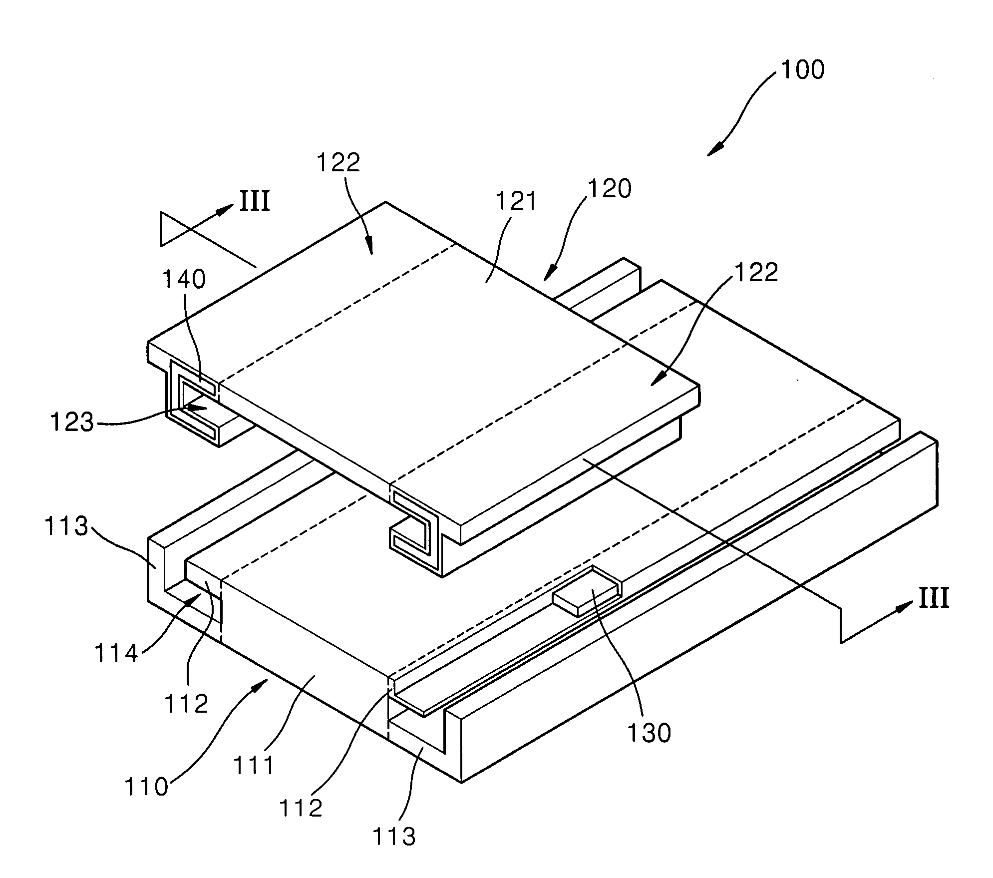
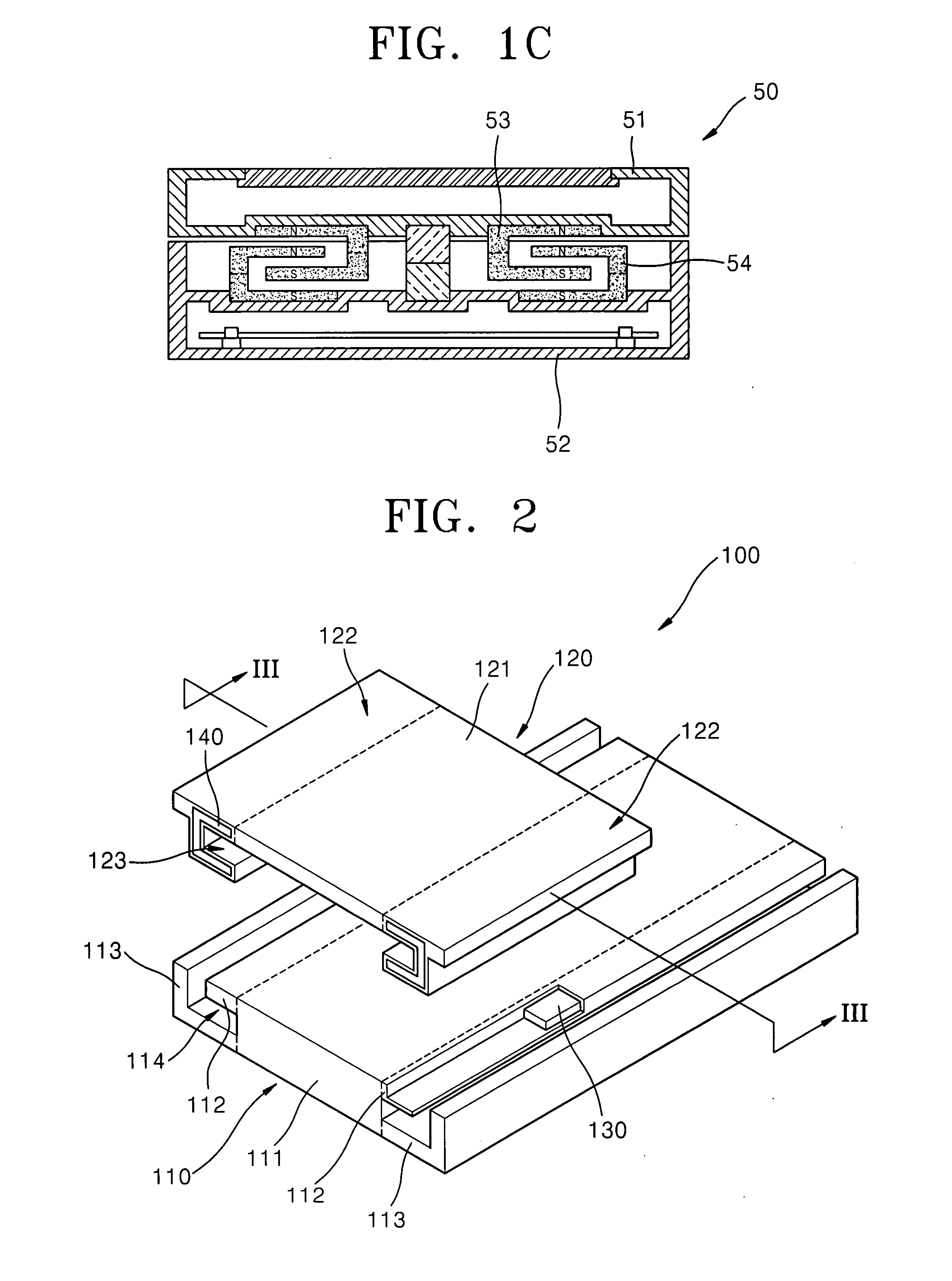
[0044]Referring to FIGS. 2 and 3, a sliding structure 100 for a mobile electronic device includes a first slider member 110 with first magnets 130; and a second slider member 120 with second magnets 140. Hereinafter, although the sliding structure 100 is described in operation with the first slider member 110 being relatively stationary and the second slider member 120 sliding on the first slider member 110, it should be appreciated that the first and second slider member 110, 120 move relative to each other. To this end, the sliding structure 100 may be operated by holding the second slider member 120 generally stationary and sliding the first slider member 110 on the second slider member 120. Furthermore, it should be appreciated that the terms up, upward, down, downward, top, bottom, right and left are used herein for ...


PUM


Abstract

A magnetic levitation sliding structure is provided. The sliding structure includes a first slider member including a guide portion with a first magnet, a second slider member including a receiving portion with a channel-shaped second magnet, the receiving portion being configured to receive the guide portion so as to slide on the first slider member. The first and second magnets are configured so that a repelling force can act there between for facilitating the sliding operation. In some embodiments the sliding structure includes at least one attraction member configured at an initial and/or final position of one of the first and second slider members. A portable electronic device including the magnetic levitation sliding structure is also provided.

Description

CROSS-REFERENCE TO RELATED PATENT APPLICATION[0001]This application claims the benefit of Korean Patent Application No. 10-2006-0124089, filed on Dec. 7, 2006, in the Korean Intellectual Property Office, the disclosure of which is incorporated herein in its entirety by reference.BACKGROUND OF THE INVENTION[0002]1. Field of the Invention[0003]The present invention relates generally to a sliding structure, and more particularly, to a magnetic levitation sliding structure.[0004]2. Description of the Related Art[0005]Due to their simple handling and attractive design, sliding structures have been used in portable electronic devices such as cellular phones, cameras, portable multimedia players (PMP) or the like.[0006]FIG. 1A is a perspective view illustrating a conventional cellular phone 10. FIG. 1B is a schematic partial see-through side view illustrating the conventional cellular phone 10 of FIG. 1A and a sliding structure 40 thereof.[0007]Referring to FIGS. 1A and 1B, the conventiona...

Claims


Application Information

Patent Timeline
IPC IPC(8): H04M1/02H01F7/02
CPCF16C29/00F16C32/0434H04M1/0237H01F7/0236H01F7/0252F16C39/063H04B1/38
Inventor CHO, SE-HOONKIM, JONG-SOON
Owner SAMSUNG TECHWIN CO LTD
Why Eureka
Try Eureka