Submerged Surface Cleaner

a technology of cleaners and submerged surfaces, applied in the field of submerged surface cleaners, can solve the problems of adding unnecessarily to the complexity and cost of cleaning cleaners, and achieve the effect of improving the cleaning effect and improving the cleaning

Inactive Publication Date: 2008-06-19
INTEGRATED POOL PRODS
View PDF5 Cites 5 Cited by
  • Summary
  • Abstract
  • Description
  • Claims
  • Application Information

AI Technical Summary

Benefits of technology

[0010]a hammer arranged to oscillate in the valve chamber, under the influence of suction flow through the valve chamber from the inlet to the outlet, between respective positi

Problems solved by technology

It is believed that the use of external floats or a float encapsulated in the moulded plastic mat

Method used


Image

  • Submerged Surface Cleaner
  • Submerged Surface Cleaner
  • Submerged Surface Cleaner

Examples


Embodiment Construction

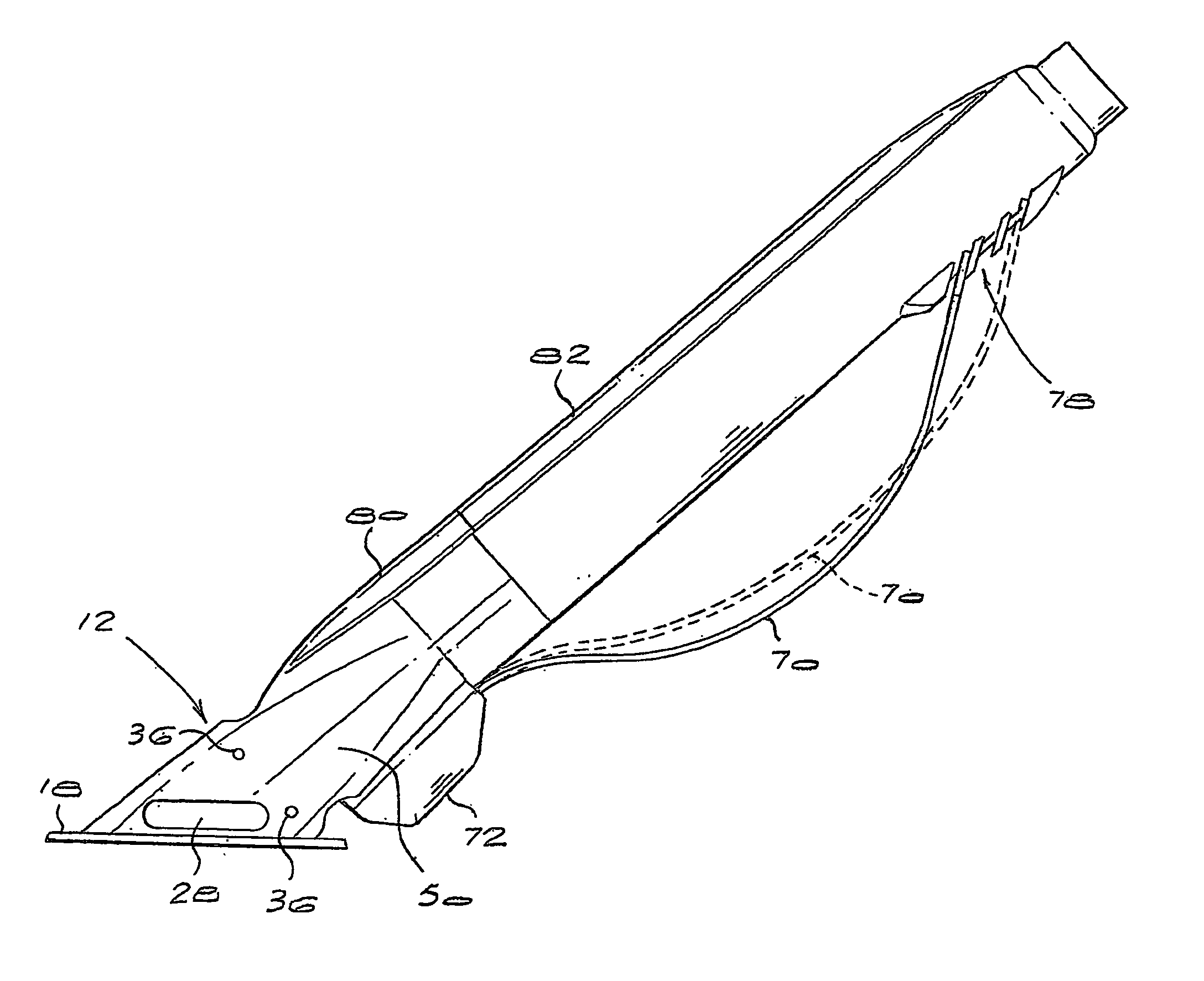
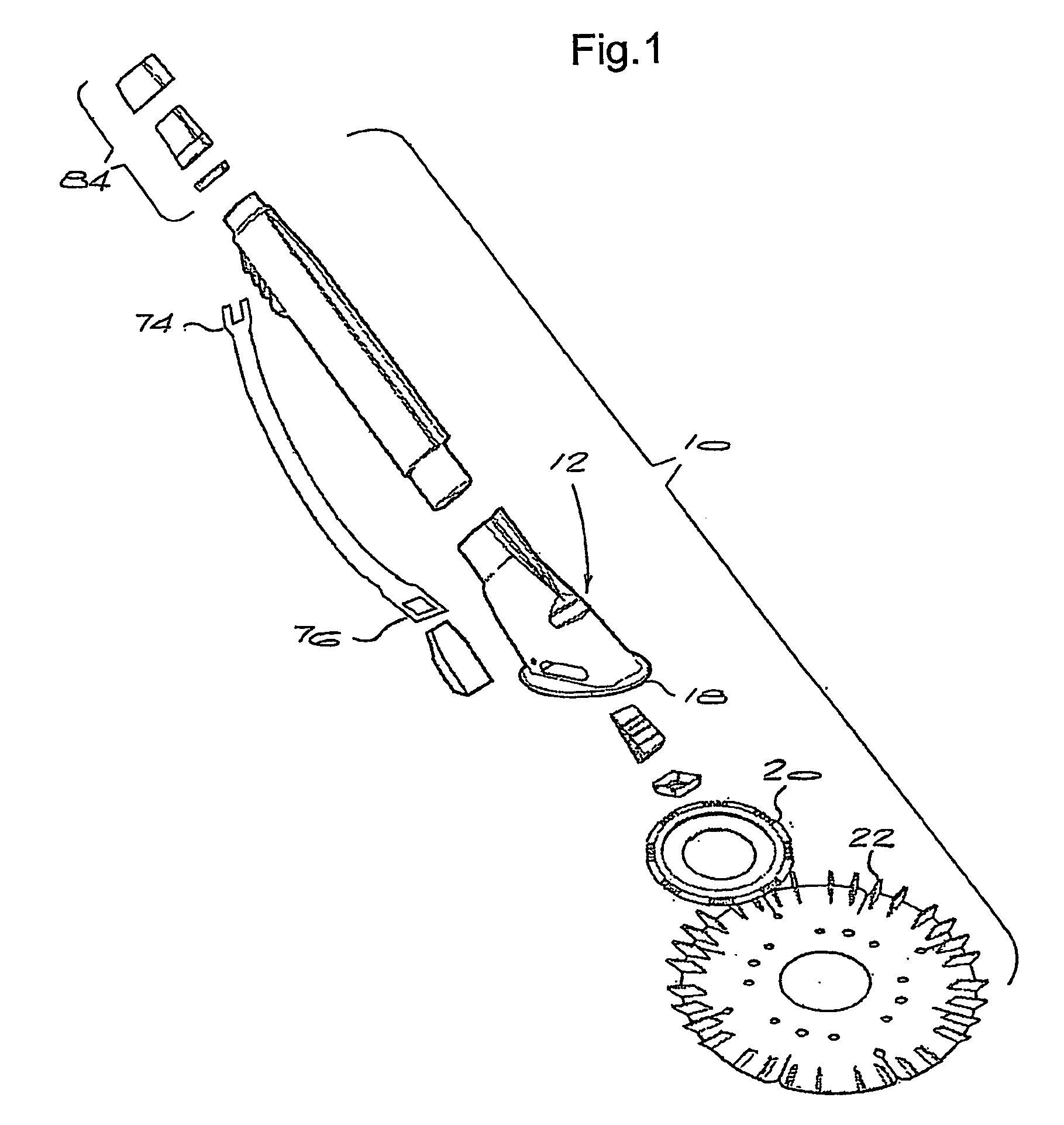
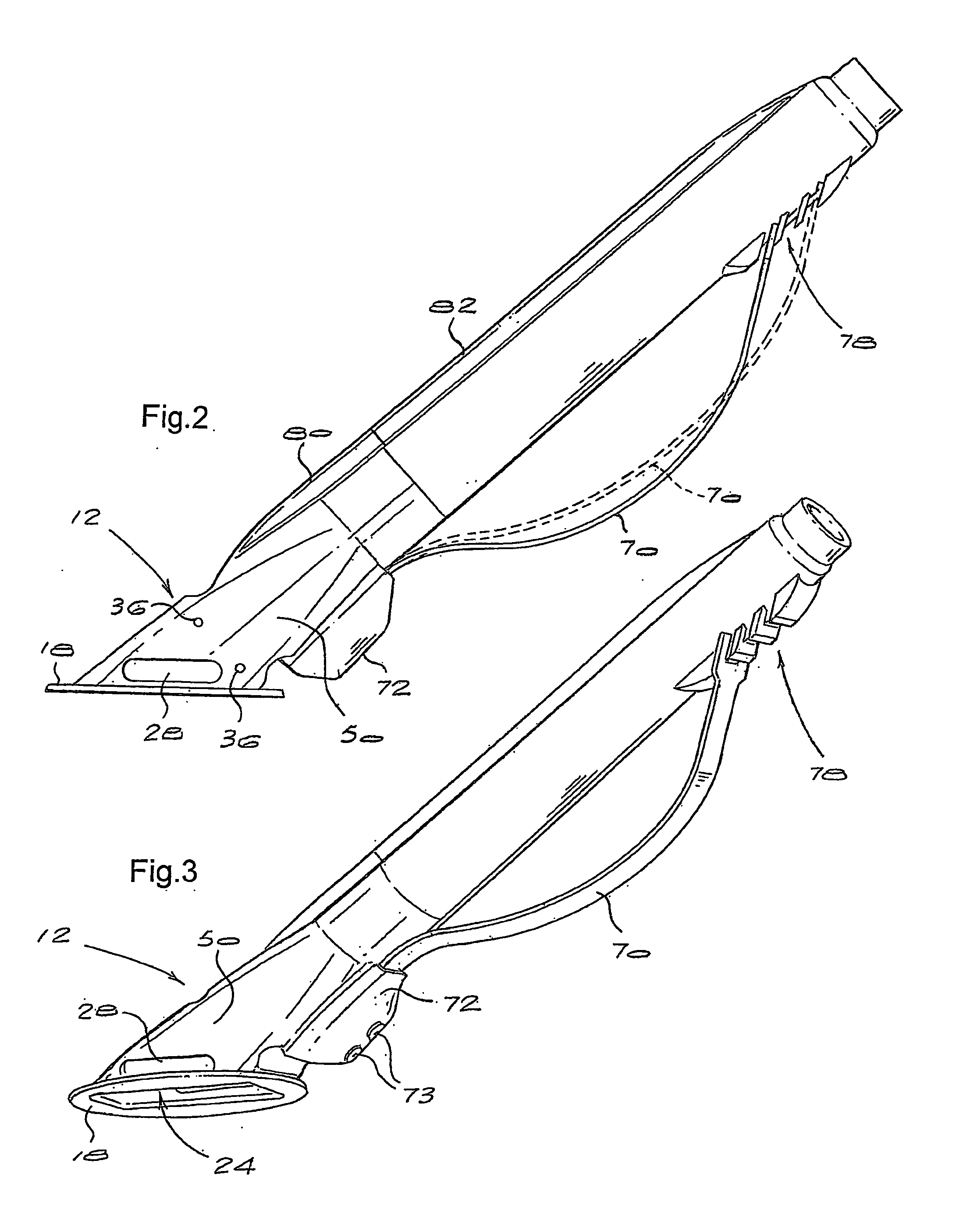
[0024]The drawings show a suction-type submerged surface cleaner 10 according to the invention.

[0025]The cleaner 10 includes a cleaner head 12 which defines a valve chamber 14 accommodating a wedge-shaped valve member or hammer 16. The cleaner head terminates at its operatively lower end in a circular foot 18 to which an annular polyurethane footpad 20 is fitted in use, with the inner extremity of a flexible polyurethane skirt 22 sandwiched between the foot and the footpad.

[0026]The foot 18 defines a generally rectangular entrance opening 24. Referring to FIG. 4, the entrance opening 24 leads to an entrance space 26 having slot-shaped openings 28 on opposite sides and leading to the valve chamber 14. An inlet to the valve chamber is provided by a central opening 30 in a cover 32 which spans across the operatively upper end of the entrance space.

[0027]The cover 32 is a separately moulded component with integral projections 34 which are clipped into holes 36 formed in the cleaner head...


PUM


Abstract

The invention concerns a suction-type submerged surface cleaner (10) which comprises an injection moulded cleaner head (12) defining internal valve chamber (14). There is a suction inlet (24) to the valve chamber, and an outlet (45) from the valve chamber. A hammer (16) is arranged to oscillate in the valve chamber under the influence of suction flow through the valve chamber from the inlet to the outlet. Contact surfaces (54) of the valve chamber walls (46, 48), which are contacted by the hammer as it oscillates, are provided internally by regions of the valve chamber walls which are reduced locally in thickness compared to other regions of the valve chamber walls. Also, at least some relatively thick regions of the valve chamber walls are formed during moulding with internal cavities to provide buoyancy for the cleaner.

Description

BACKGROUND TO THE INVENTION[0001]THIS invention relates to a submerged surface cleaner.[0002]The invention relates in particular to a suction-type submerged surface cleaner, typically for use in cleaning the submerged surfaces of a swimming pool. Suction-type cleaners are well known and have been in widespread use for a number of years.[0003]The most popular suction-type pool cleaners are connected by a flexible hose to a suction point, typically a suction inlet at the weir of the swimming pool. The cleaner operates on the submerged surface and water is sucked through it by the pump of the swimming pool filtration unit. One particularly popular pool cleaner has a valve chamber with an inlet, adjacent the submerged surface, through which a water flow is sucked and accommodating a valve member or hammer which oscillates under the influence of the suction flow and which directs the flow alternately to one or the other of a pair of outlet passages leading away from the valve chamber to ...

Claims


Application Information

Patent Timeline
IPC IPC(8): E04H4/16
CPCE04H4/1663
Inventor SUPRA, CARL FREDERICK WILHELM
Owner INTEGRATED POOL PRODS
Why Eureka
Try Eureka