Optical element

a technology of optical elements and display screens, applied in the field of optical elements, can solve the problems of disadvantageous visible right end of display screens, unsatisfactory for the user of devices,

Inactive Publication Date: 2008-06-19
NEC LCD TECH CORP
View PDF16 Cites 44 Cited by
  • Summary
  • Abstract
  • Description
  • Claims
  • Application Information

AI Technical Summary

Benefits of technology

[0012]An exemplary object of the present invention is to provide an optical element that can prevent the entire display screen from being visible when viewed obliquely from a position in front of the display screen.

Problems solved by technology

However, in a device designed to be used by an individual, such as a mobile phone, a large angle of the field of view may allow others to peep at displayed information, which may be unpleasant to the user of the device.
Therefore, even when the microlouver is attached onto the display screen, the right end of the display screen is disadvantageously visible when viewed obliquely from a position in front of the display screen.

Method used


Image

  • Optical element
  • Optical element
  • Optical element

Examples


first exemplary embodiment

[0041]FIG. 4 is a cross-sectional view showing the optical element according to a first exemplary embodiment of the present invention. FIG. 5 is a plan view of the microlouver shown in FIG. 4.

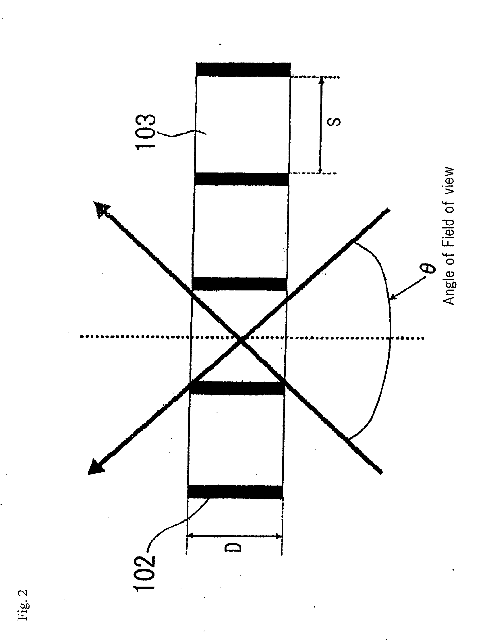
[0042]The optical element of this exemplary embodiment includes microlouver 1 having a periodic structure in which linear light absorbing layers 2 and linear transparent layers 3 are alternately disposed in one direction, and diffusion layer 4 attached onto microlouver 1. In microlouver 1 in this exemplary embodiment, light absorbing layer 2 and transparent layer 3 are periodically disposed at a fixed pitch. Furthermore, in microlouver 1 of this exemplary embodiment, the ratio of width S of transparent layer 3 to thickness D of microlouver 1 is smaller than that of a typical microlouver. Therefore, across microlouver 1 in this exemplary embodiment, the angle of the field of view of the light passing through transparent layers 3 is smaller than that in a typical microlouver. Transparent substrat...

second exemplary embodiment

[0079]FIG. 15 is a cross-sectional view showing the optical element according to a second exemplary embodiment of the present invention.

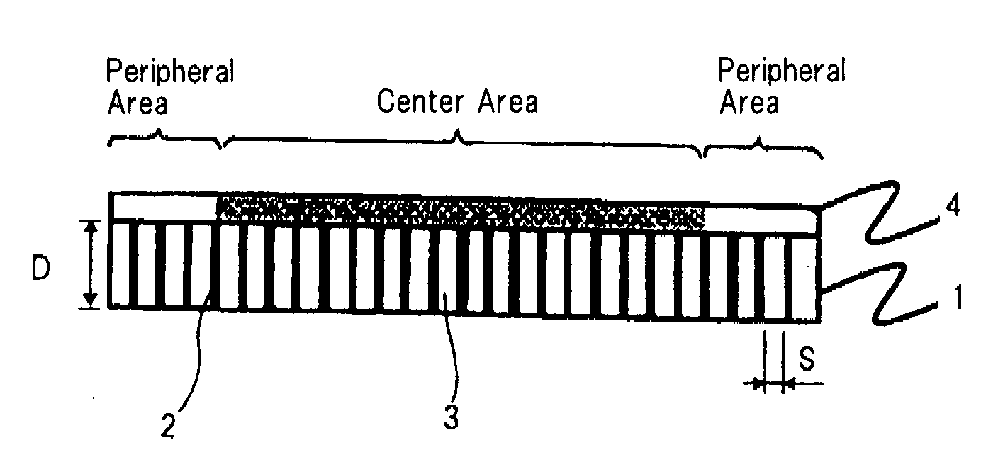
[0080]The optical element of this exemplary embodiment includes microlouver 1 having a periodic structure in which linear light absorbing layers 2 and linear transparent layers 3 are alternately disposed in one direction, and diffusion layer 4 attached onto microlouver 1. The width of transparent layer 3 in microlouver 1 of this exemplary embodiment is larger in the central area while smaller in the peripheral area. Therefore, in microlouver 1 in this exemplary embodiment, the angle of the field of view of the light passing through transparent layers 3 is large in the central area while smaller in the peripheral area.

[0081]Diffusion layer 4 in this exemplary embodiment is configured in such a way that the diffusion power in the peripheral area of the optical element is lower than that in the central area in the right / left direction in FIG. 15. Since...


PUM


Abstract

An optical element includes a microlouver including transparent layers and light absorbing layers alternately disposed, the light absorbing layers constraining the extent of the direction in which light passing through the transparent layers exits, and a diffusion layer provided on the microlouver. The angle of the field of view varies in such a way that the angle of the field of the view light passing thorough the peripheral area of the optical element is smaller than the angle of the field of view of light passing thorough the central area of the optical element.

Description

[0001]This application is based upon and claims the benefit of priority from Japanese Patent Application No. 2006-287694 filed on Oct. 23, 2006, the content of which is incorporated by reference.BACKGROUND OF THE INVENTION[0002]1. Field of the Invention[0003]The present invention relates to an optical element including a microlouver that constrains the extent of the direction of exiting transmitted light. The present invention further relates to an illumination optical device using such an optical element and a display device, represented by a liquid crystal display (LCD) and a plasma display, using such an optical element.[0004]2. Description of the Related Art[0005]Liquid crystal displays are used as the display devices of various information processing devices, such as mobile phones, personal digital assistances (PDAs), automatic teller machines (ATMs), and personal computers. In recent years, there have been commercialized liquid crystal displays in which the angle of the field ...

Claims


Application Information

Patent Timeline
Patent Type & Authority Applications(United States)
IPC IPC(8): G02B5/02
CPCG02B5/005G02B5/0231G02F1/133524G02B5/0278G02F1/133504G02B5/0252
Inventor MIMURA, KOJISUMIYOSHI, KEN
Owner NEC LCD TECH CORP
Why Eureka
Try Eureka