
Time division duplex forward-to-reverse transition signal generator

a technology of reverse transition signal and forward-to-reverse transition signal, which is applied in the field of time division duplex wireless communications system and method, can solve the problems of reducing the coverage area of the reverse link, and reducing the noise of the reverse link

Inactive Publication Date: 2008-06-19
INTEL CORP
View PDF5 Cites 14 Cited by
  • Summary
  • Abstract
  • Description
  • Claims
  • Application Information

AI Technical Summary

Benefits of technology

[0011]In one aspect, embodiments of the invention provide a transition signal generator. The transition signal generator includes a signal sampler for sampling a time division duplex signal from a signal path in a communica

Problems solved by technology

Since both the forward and reverse links share the same signal path, this transport loss also complicates the reverse link.
Transport loss increases reverse link noise figures thus reducing the reverse link coverage area.
Given the base station variants available from manufacturers, some site requirements may still not be met in a cost effective way.
Boosters however are generally add-on devices with little or no coordinating communication with the base station equipment.
This presents a problem when adding booster equipment to TDD base stations.
In general however, this approach is not suitable since the separate data information from the base station regarding when the common signal path is used by the forward link, or conversely the reverse link, is not available.

Method used


Image

  • Time division duplex forward-to-reverse transition signal generator
  • Time division duplex forward-to-reverse transition signal generator
  • Time division duplex forward-to-reverse transition signal generator

Examples


Embodiment Construction

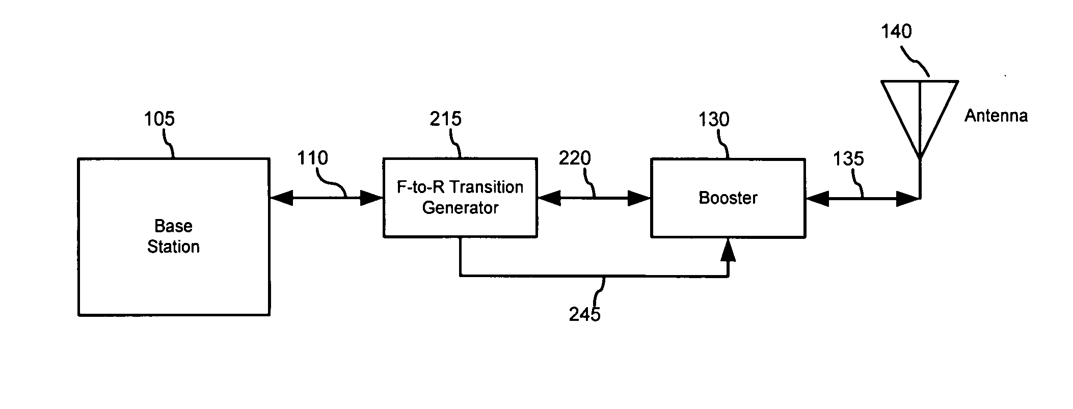
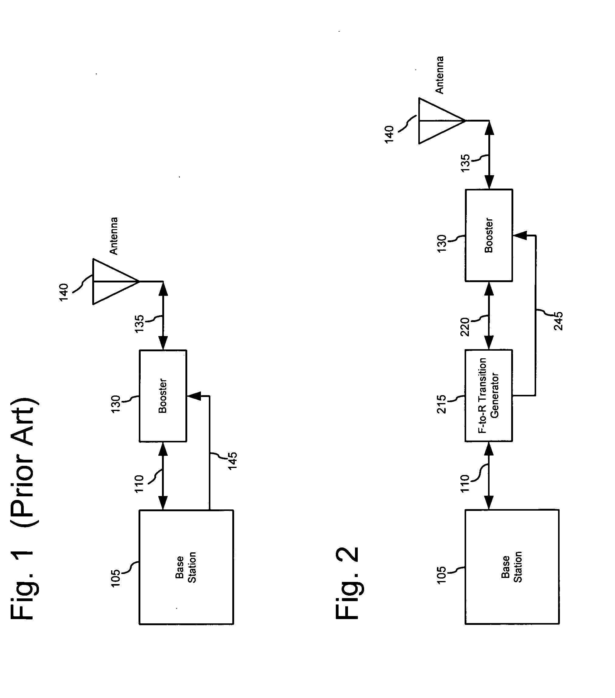
[0028]The present invention addresses the above problem and provides a system and method which generates a forward-to-reverse link transition signal by monitoring the common line. This link transition signal can then be provided to a TDD booster thereby enabling booster operation. Accordingly the present invention also provides an improved base station and transmitter equipped with a booster.

[0029]FIG. 2 is a block diagram including a base station 105, a forward-to-reverse transition signal generator 215, a booster 130, and an antenna 140. The base station 105 in FIG. 2 does not include a logic signal output, or the logic signal output is not used. As before, the base station 105 operates with a TDD signal link connected on path 110. The base station TDD signal link is connected to a forward-to-reverse (F-to-R) transition signal generator 215. The TDD signal link passes through the signal generator 215 without modification, but perhaps with some attenuation, for connection to the bo...


PUM


Abstract

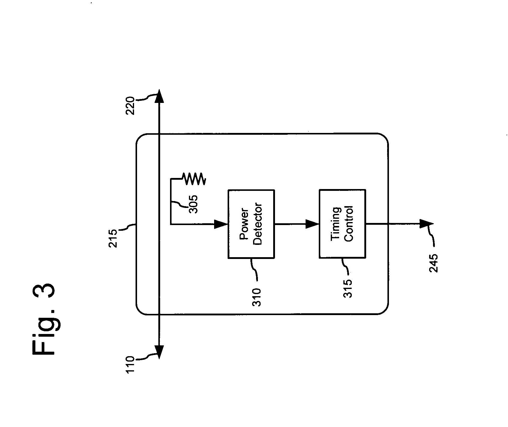
A transition signal generator is used to for controlling a booster of a time division duplex signal in a communications system. The transition signal generator includes a signal sampler for sampling the time division duplex signal, a power detector for detecting a power of the sampled signal, and a timing control unit for generating a logic signal indicating a direction of the sampled signal from the detected power of the sampled signal.

Description

CROSS-REFERENCE TO RELATED APPLICATION[0001]The present application claims priority under 35 USC section 119(e) to U.S. Provisional Patent Application Ser. No. 60 / 874,557, filed Dec. 13, 2006, the disclosure of which is herein incorporated by reference in its entirety.BACKGROUND OF THE INVENTION[0002]1. Field of the Invention[0003]The present invention relates generally to wireless communications systems and methods. More specifically, the invention relates to time division duplex wireless communications systems and methods.[0004]2. Description of Related Art[0005]Many modern wireless communication systems are moving to Time Division Duplex (TDD) to provide two-way communication between a base station and remote stations. In TDD systems, the same carrier frequency is used for both base-to-remote and remote-to-base radio links. These links are generally referred to as forward and reverse radio links, respectively. The two radio links share the same carrier frequency by alternately sh...

Claims


Application Information

Patent Timeline
IPC IPC(8): H04J3/00
CPCH04B1/48H04B1/18
Inventor HUNTON, MATTHEW J.CARICHNER, SCOTT
Owner INTEL CORP
Learn More