Fastening device

a technology of fastening device and fastening wire, which is applied in the direction of fastening wire, nails, electrical equipment, etc., can solve the problems of complex structure, difficult operation for users, and the variety of equipment and electronic devices becoming slim and small to meet the customer's requirements, and achieves the effect of convenient operation for users

Inactive Publication Date: 2008-06-19
LOTES
View PDF0 Cites 11 Cited by
  • Summary
  • Abstract
  • Description
  • Claims
  • Application Information

AI Technical Summary

Benefits of technology

[0008]One particular aspect of the present invention is to provide a fastening device. Its structure is simple. The required space is small. It can firmly fasten the fastened object. It is easy for the user to operate it.
[0010]The fastening device of the present invention merely includes the fastening part and the tightly-locking part. Its structure is simple, and the required space is small. When the user uses the fastening device, the user merely needs to pass one end of the tightly-locking part through the main body portion of the fastening part and positions it onto the positioning hole of the circuit board, and make the second end of the tightly-locking part to fit with the buckling portion and tightly lock the fastened object. The procedure is simple. Because the fastening part cooperates with the tightly-locking part, the fastening device firmly fastens the fastened object, such as an electronic card.

Problems solved by technology

As the technology has been highly developed, a variety of equipments and electronic devices become slim and small to meet the customer's requirements.
But the shortcoming of the fastening device is its structure is complex and it is difficult for the user to operate it.

Method used


Image

  • Fastening device
  • Fastening device
  • Fastening device

Examples


Embodiment Construction

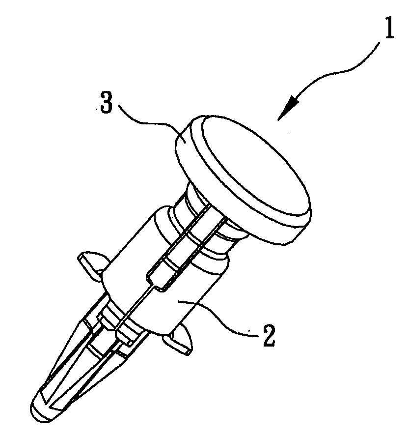
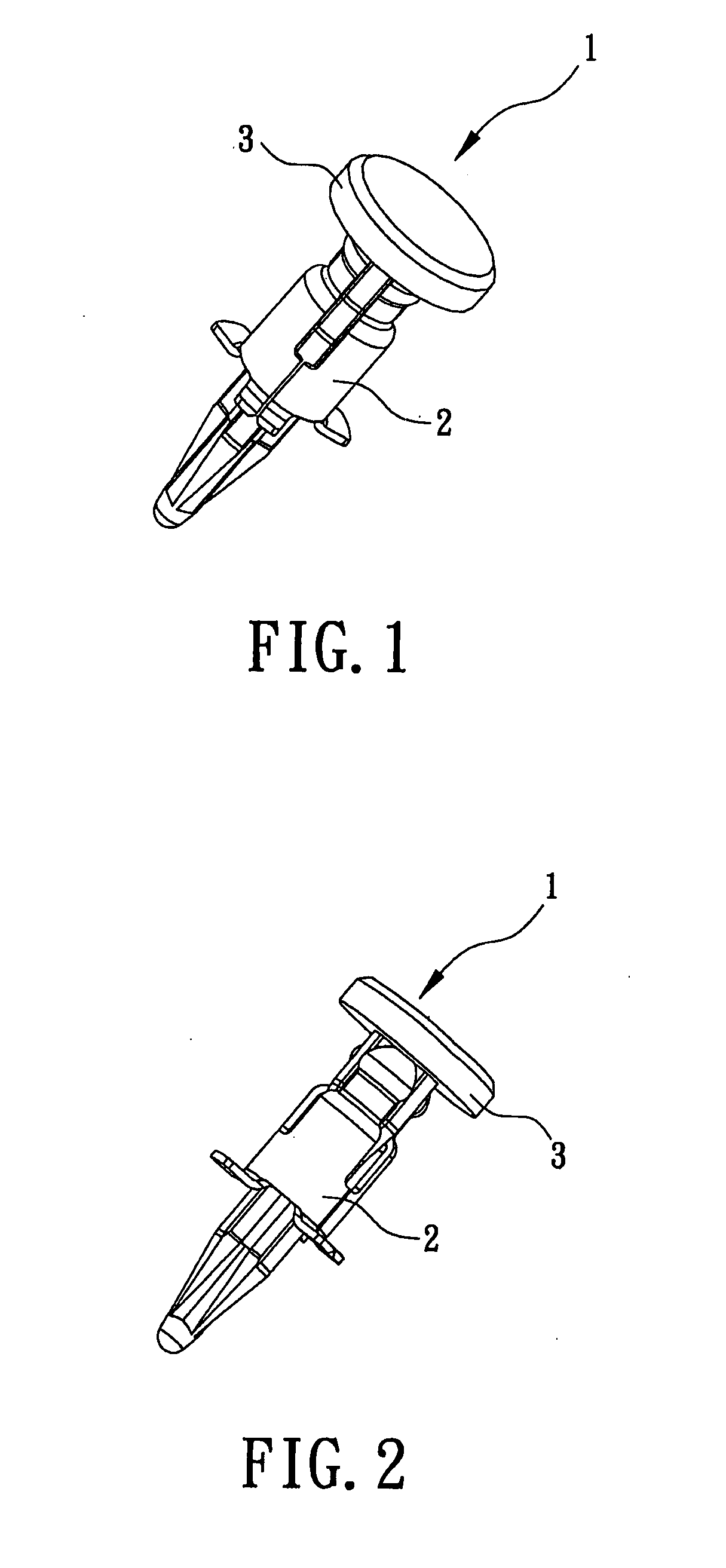
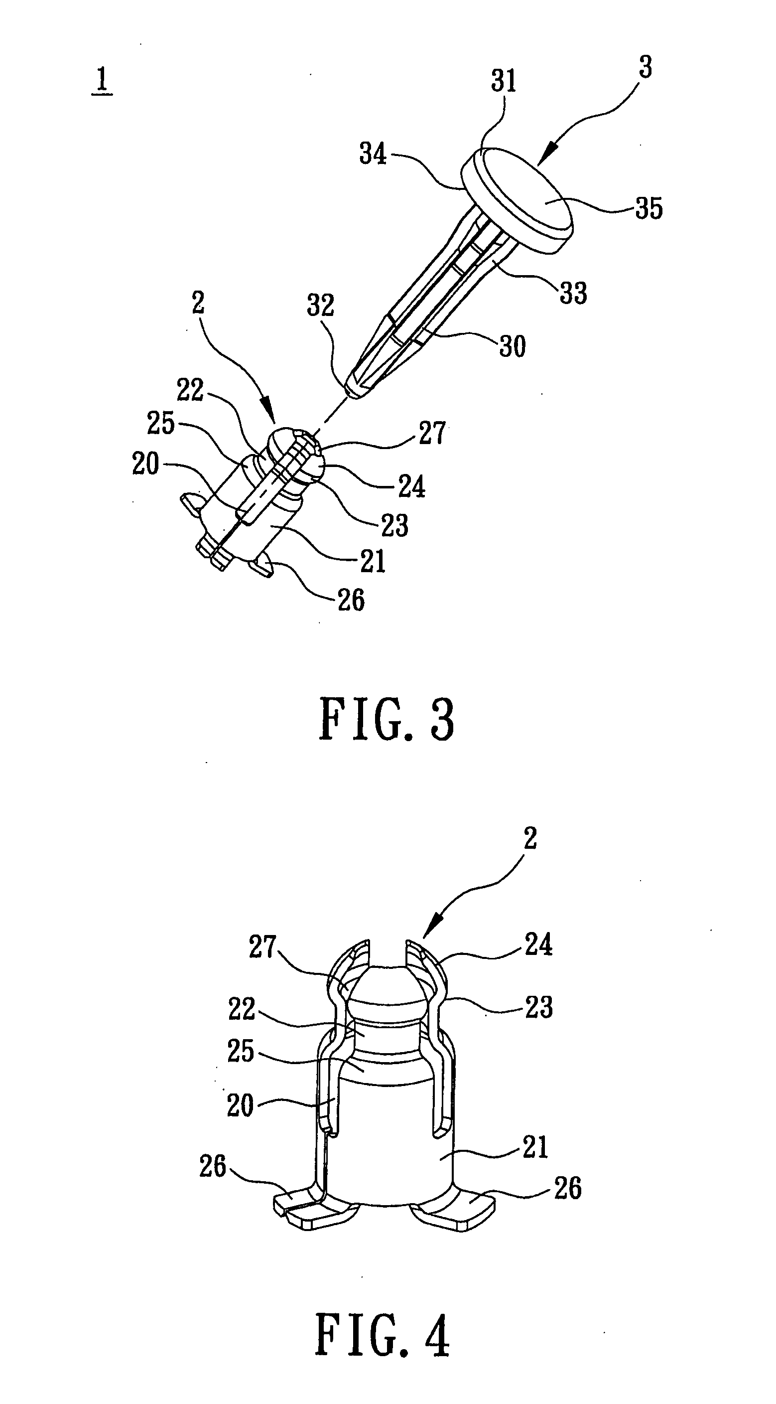
[0021]Reference is made to FIGS. 1˜8. The fastening device 1 is used for fastening a fastened object (in this embodiment, the fastened object is an electronic card 6, alternatively, it also can be another object, such as a circuit board) on a circuit board 4. The fastening device 1 includes a fastening part 2 for fastening the fastened object and a tightly-locking part 3 fitting with the fastening part 2.

[0022]The fastening part 2 is a flexible part that has a column shape. The fastening part 2 includes a main body portion 21. The main body portion 21 extends to form a wedging portion 22. An end of the wedging portion 22 extends to form a buckling portion 23. On end of the buckling portion 23 that is far away from the main body portion 21 extends to form a guiding portion 24 that can guide the fastened object into the buckling portion 23. The guiding portion 24 is convex upwards and has an arc shape. The buckling portion 23 is concave downwards and has an arc shape. A contacting and...


PUM


Abstract

A fastening device is used for fastening a fastened object on a circuit board. The fastening device includes a fastening part for fastening the fastened object. The fastening part includes a main body portion. The main body portion extends to form a wedging portion. An end of the wedging portion extends to form a buckling portion. The fastening device also includes a tightly-locking part that fits with the fastening part. One end of the tightly-locking part passes through the main body portion of the fastening part and is positioned on the positioning hole of the circuit board. The second end of the tightly-locking part fits with the buckling portion to tightly lock the fastened object. The fastening device of the present invention merely includes the fastening part and the tightly-locking part. Its structure is simple, and the required space is small.

Description

BACKGROUND OF THE INVENTION[0001]1. Field of the Invention[0002]The present invention relates to a fastening device.[0003]2. Description of the Related Art[0004]As the technology has been highly developed, a variety of equipments and electronic devices become slim and small to meet the customer's requirements. Even though the functions and components are added to the electronic devices, the electronic devices still has a low height and a small dimension, especially for a portable electronic device.[0005]Interface cards are the communication bridges between the motherboard and the peripherals. With the portable electronic devices become slim more and more, the miniaturization of the interface cards is also needed.[0006]At present, the interface card with a Mini PCI format that is popularly applied to the laptop has a traverse-plugging design. The positioning hole for connecting the interface card with the electrical connector on the motherboard is traverse. After the interface card i...

Claims


Application Information

Patent Timeline
Patent Type & Authority Applications(United States)
IPC IPC(8): F16B15/02
CPCH05K7/142F16B5/065
Inventor JIN, ZUOFENG
Owner LOTES
Why Eureka
Try Eureka