Mobile communication terminal and mobile communication method

a mobile communication and terminal technology, applied in the direction of transmission monitoring, receiver monitoring, electrical equipment, etc., can solve the problems the difficulty of ensuring the accuracy of measuring the path timing and the reception level, and the likely deformation of the measurement accuracy. to occur, so as to improve the communication quality

Inactive Publication Date: 2008-06-19
NTT DOCOMO INC
View PDF6 Cites 12 Cited by
  • Summary
  • Abstract
  • Description
  • Claims
  • Application Information

AI Technical Summary

Benefits of technology

[0013]Thus, the present invention has been made in view of these trade-off situations, and aims to provide a mobile communication terminal and a mobile communication method capable of improving communication quality by ensuring accuracy in measuring the path timings and the reception qualities regardless of the moving speed.

Problems solved by technology

Such degradation in measurement accuracy is likely to occur especially when the mobile communication terminal receives a radio signal of a high frequency band, such as the 2 GHz band, while moving at an extremely high speed (for example, at 200 km / h or more).
In such a ease, the S / N ratio of the radio signal is deteriorated while the mobile communication terminal does not move at all or is moving at a low speed (referred to below as “time of low-speed movement”), leading to degradation in accuracy in measuring the path timing.
In other words, there has been a problem that ensuring accuracy in measuring the path timings and the reception levels is difficult at both times of high-speed movement and low-speed movement of the mobile communication terminal.
The mobile communication terminal is unable to appropriately select some of multipaths for demodulation when accuracy in measuring the path timings is degraded.
Additionally, the mobile communication terminal is unable to select a suitable radio base station when accuracy in measuring the reception levels is degraded.
For these reasons, communication quality is deteriorated (for example, deterioration in SIR and BLER, and lowered throughput).

Method used


Image

  • Mobile communication terminal and mobile communication method
  • Mobile communication terminal and mobile communication method
  • Mobile communication terminal and mobile communication method

Examples


Embodiment Construction

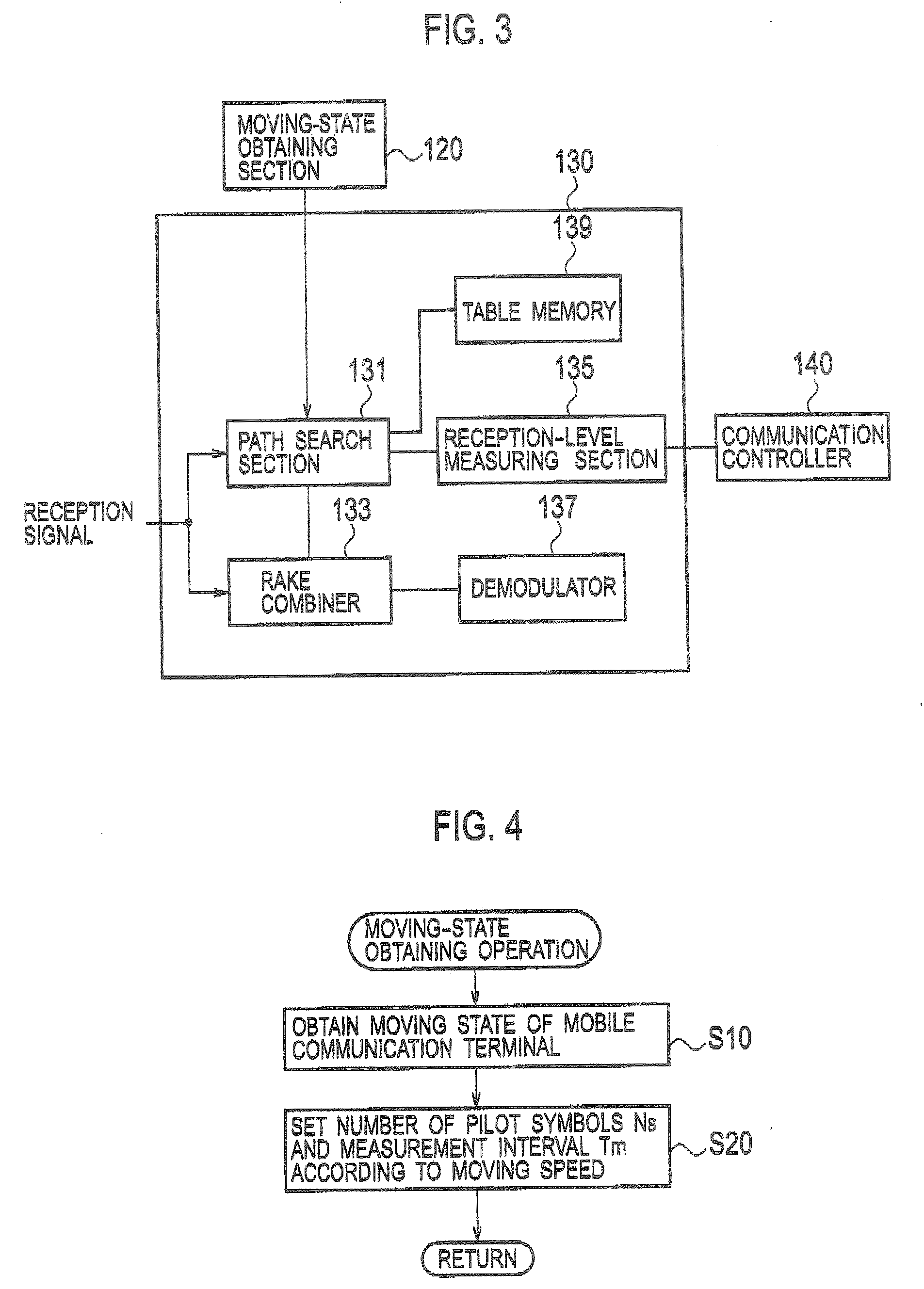
[0030]Next, an explanation will be given for an embodiment of the present invention. The same or similar symbols are given to the same or similar portions in the description of the drawings below. It should be noted that the drawings are schematic, and that the dimensional ratios and the like are different from the actual ones.

[0031]Accordingly, specific dimensions and the like should be determined in consideration of the following description. In addition, portions in which dimensional relations and ratios between the drawings differ are included, as a matter of course.

(Overall Schematic Configuration of Mobile Communication System)

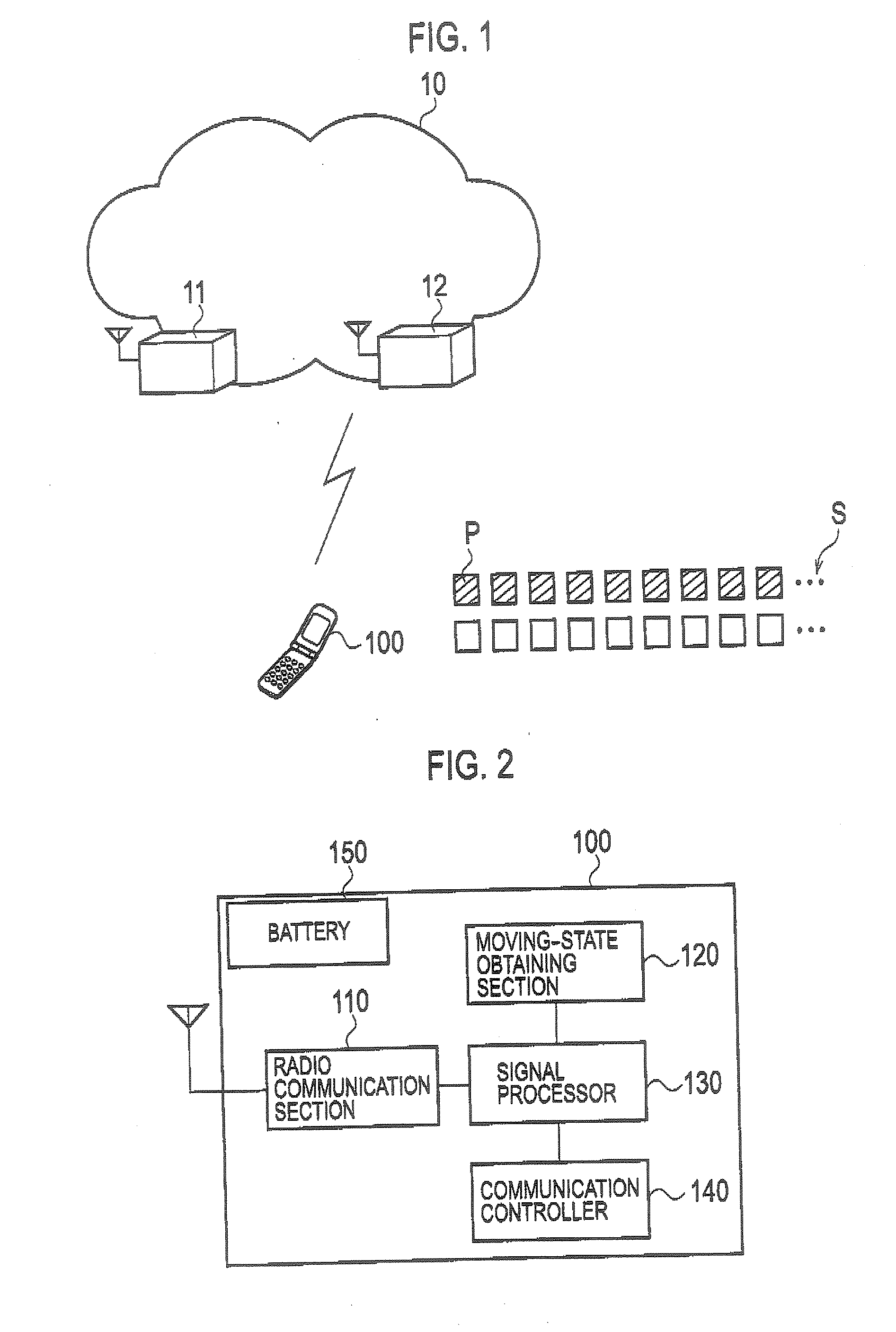
[0032]FIG. 1 is an overall schematic configuration diagram of a mobile communication system according to the present invention. As shown in FIG. 1, the mobile communication system according to the present invention is configured of a communication network 10, radio base stations 11 and 12, and a mobile communication terminal 100.

[0033]The communication n...


PUM


Abstract

Provided is a mobile communication terminal including: a moving-state obtaining section for obtaining a moving state of the mobile communication terminal; a path search section for determining a measurement condition including any one of the number of known signals and an interval for measuring the radio signal according to the moving state obtained by the moving-state obtaining section; and a reception-level measuring section and a demodulator for performing signal processing by use of the radio signal under the measurement condition determined by the path search section. The known signal is used for estimating the influence of propagation path of the received radio signal, and has setting values that are known by both the transmitting side and receiving side.

Description

CROSS REFERENCE TO RELATED APPLICATION[0001]This application is based upon and claims the benefit of priority from the prior Japanese Patent Applications No. 2006-336279 filed on Dec. 13, 2006 and No. 2007-321385 filed on Dec. 12, 2007; the entire contents of which are incorporated herein by reference.BACKGROUND OF THE INVENTION[0002]1. Field of the Invention[0003]The present invention relates to a mobile communication terminal and a mobile communication method capable of controlling communications according to states of radio signals including a known signal by receiving the radio signals from radio base stations. The known signal is a signal used for estimating an influence caused by a propagation path of a received radio signal. Setting values for the known signal are known by both the transmitting side and the receiving side.[0004]2. Description of the Related Art[0005]For a mobile communication system, a conventional method has been known, in which time-series data of received ...

Claims


Application Information

Patent Timeline
Patent Type & Authority Applications(United States)
IPC IPC(8): H04Q7/20H04W36/00H04W36/32
CPCH04W36/0088H04B17/364H04B17/27H04W36/32
Inventor SHIMOMURA, TETSUTOOKUMURA, YUKIHIKO
Owner NTT DOCOMO INC
Why Eureka
Try Eureka