Architecture for a Physical Interface of a High Speed Front Side Bus

Inactive Publication Date: 2008-06-19
IBM CORP
View PDF5 Cites 4 Cited by
  • Summary
  • Abstract
  • Description
  • Claims
  • Application Information

AI Technical Summary

Benefits of technology

[0006]The present invention provides a high speed computer processor system with a high speed interface for a

Problems solved by technology

Without a higher speed interface connection the computer gaming industry will not be abl

Method used


Image

  • Architecture for a Physical Interface of a High Speed Front Side Bus
  • Architecture for a Physical Interface of a High Speed Front Side Bus
  • Architecture for a Physical Interface of a High Speed Front Side Bus

Examples


Embodiment Construction

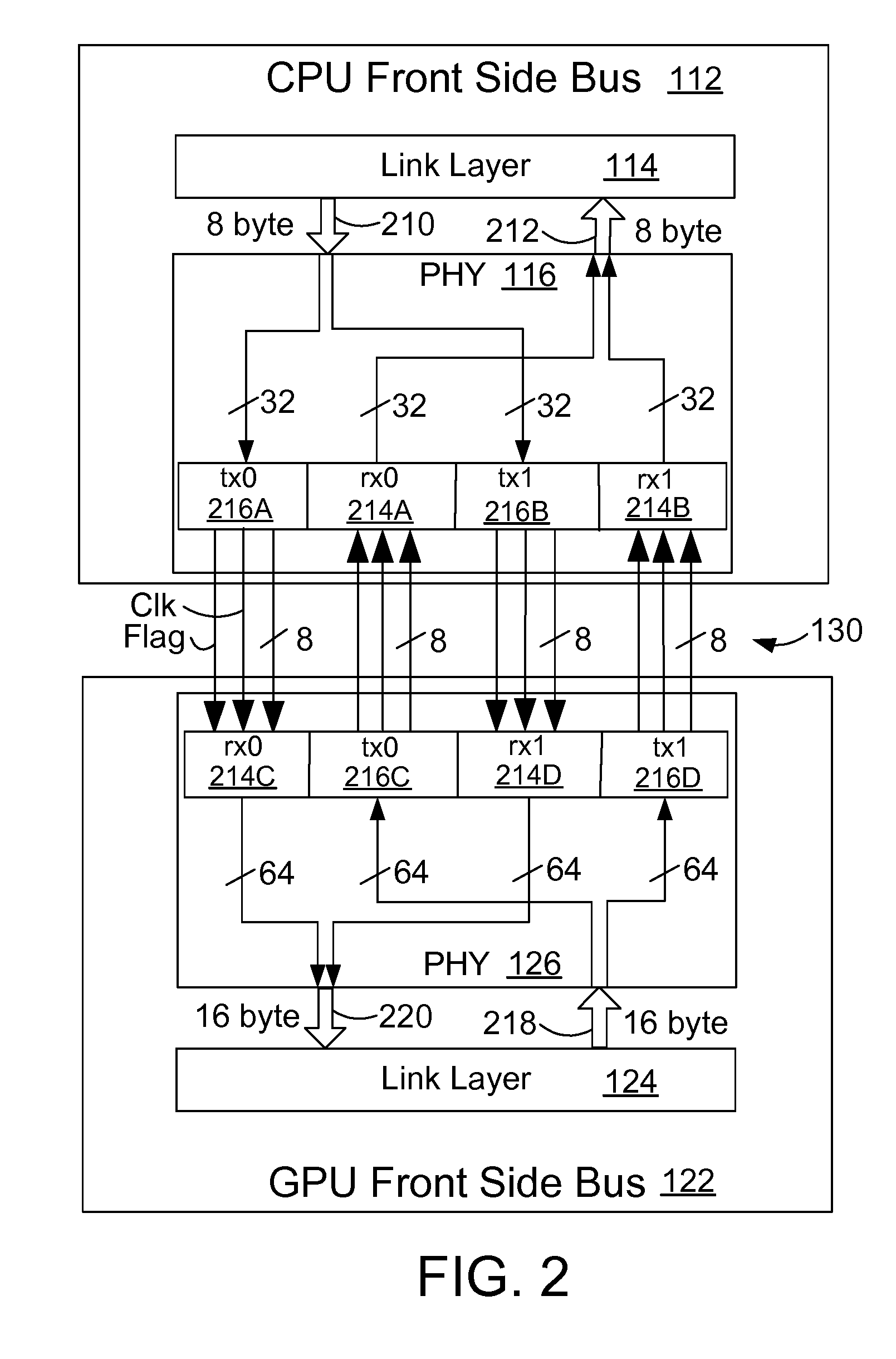
[0013]FIG. 1 illustrates a block diagram of a computer system 100 according to a preferred embodiment. The computer system 100 includes a central processing unit (CPU) 110. The CPU 110 is connected to a graphics processor unit (GPU) 120 with a front side bus interconnect or channel 130. The illustrated embodiment shows a single CPU 110 but it is understood that multiple processors could be used. The GPU 120 is connected to a south bridge 140. The south bridge 140 has other connections 145 to various peripherals such as game controllers, and disk drives (not shown). The GPU 120 is also connected to main memory 150.

[0014]The CPU 110 includes a front side bus (FSB) 112 to interface to the FSB interconnect 130. The FSB 112 includes a link layer 114 that controls the protocol and link initialization. The link layer 114 connects to the physical layer (PHY) 116 that accepts the digital signals from the link layer 114 and drives the signals on the FSB channel 130 to the GPU 120. The GPU 120...


PUM


Abstract

A high speed computer processor system includes a high speed interface for a graphics processor. In a preferred embodiment, the high speed interface includes a front side bus (FSB) that interfaces to a similar high speed interface on the graphics processor.

Description

BACKGROUND OF THE INVENTION[0001]1. Technical Field[0002]This invention generally relates to computer systems, and more specifically relates to an architecture for a physical interface of a high speed front side bus.[0003]2. Background Art[0004]Computer processors and computer systems are constantly evolving and improving. Ever faster computer processor systems are needed in the computer gaming industry to provide continued improvement in gaming performance.[0005]The computer gaming industry has a need for a high speed processor with a high speed interface that can readily interface with a graphics processor. Without a higher speed interface connection the computer gaming industry will not be able to continue to offer continuing quality improvements to the computer gaming experience.DISCLOSURE OF INVENTION[0006]The present invention provides a high speed computer processor system with a high speed interface for a graphics processor. Embodiments are directed to a computer processor s...

Claims


Application Information

Patent Timeline
IPC IPC(8): G06F13/36
CPCG06F13/4204Y02B60/1235Y02B60/1228Y02D10/00
Inventor BAUMGARTNER, STEVEN JOHNBONACCIO, ANTHONY RICHARDBUCHHOLTZ, TIMOTHY CLYDEDREPS, DANIEL MARKGEER, CHARLES PORTERMEGHELLI, MOUNIRRYLOV, SERGEY VLADIMIROVICHSILJENBERG, DAVID W.WOESTE, DANA MARIE
Owner IBM CORP
Why Eureka
Try Eureka