Gas tank having usage monitoring system

a gas tank and monitoring system technology, applied in the field of storage devices, can solve the problems of high maintenance fee, degraded gas tank integration, and high maintenance fee, and achieve the effect of preventing gas from passing through

Inactive Publication Date: 2008-06-26
KIM HYEUNG YUN
View PDF31 Cites 13 Cited by
  • Summary
  • Abstract
  • Description
  • Claims
  • Application Information

AI Technical Summary

Problems solved by technology

However, the integrity of the gas tank may be degraded due to various types of physical damages, such as mechanical impacts and fatigue accumulated in the tank components due to repeated filling / emptying cycles.
These approaches have a difficulty in that, as the gas tank needs to be disassembled from the integral system for inspection, a regular checkup of the tank can be a significant task and quite complicated to result in a high maintenance fee.
Also, these approaches might be ineffective and unreliable since they fail to consider the actual operational and environmental conditions of the gas tank, where the structural integrity of the tank may be significantly affected by these conditions.

Method used


Image

  • Gas tank having usage monitoring system
  • Gas tank having usage monitoring system
  • Gas tank having usage monitoring system

Examples


Embodiment Construction

[0021]Although the following description contains many specifics for the purposes of illustration, those of ordinary skill in the art will appreciate that many variations and alterations to the following detains are within the scope of the invention. Accordingly, the following embodiments of the invention are set forth without any loss of generality to, and without imposing limitation upon, the claimed invention.

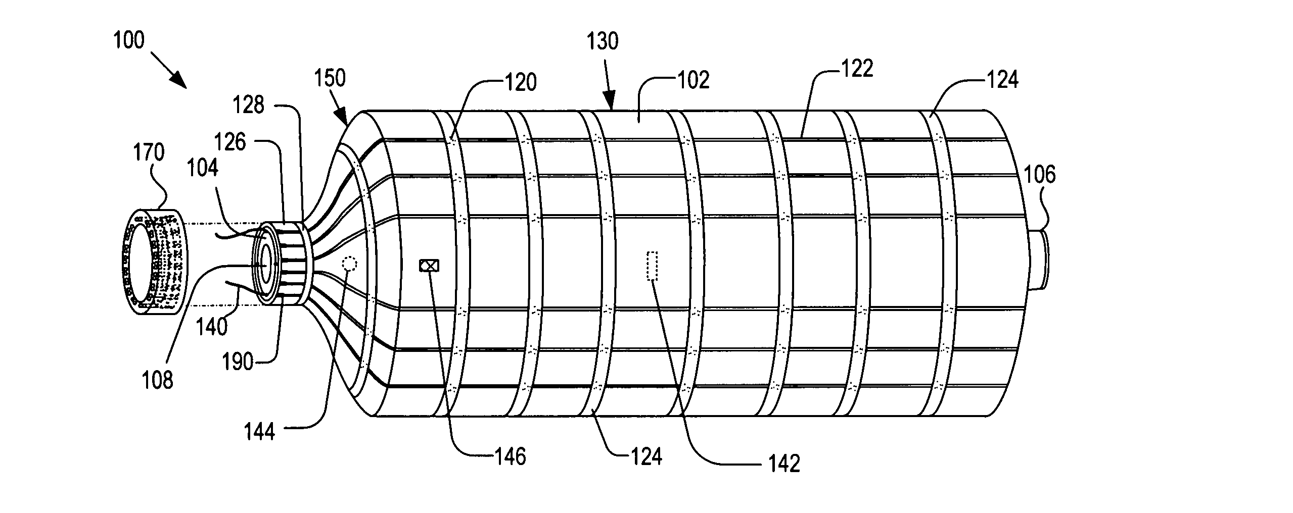
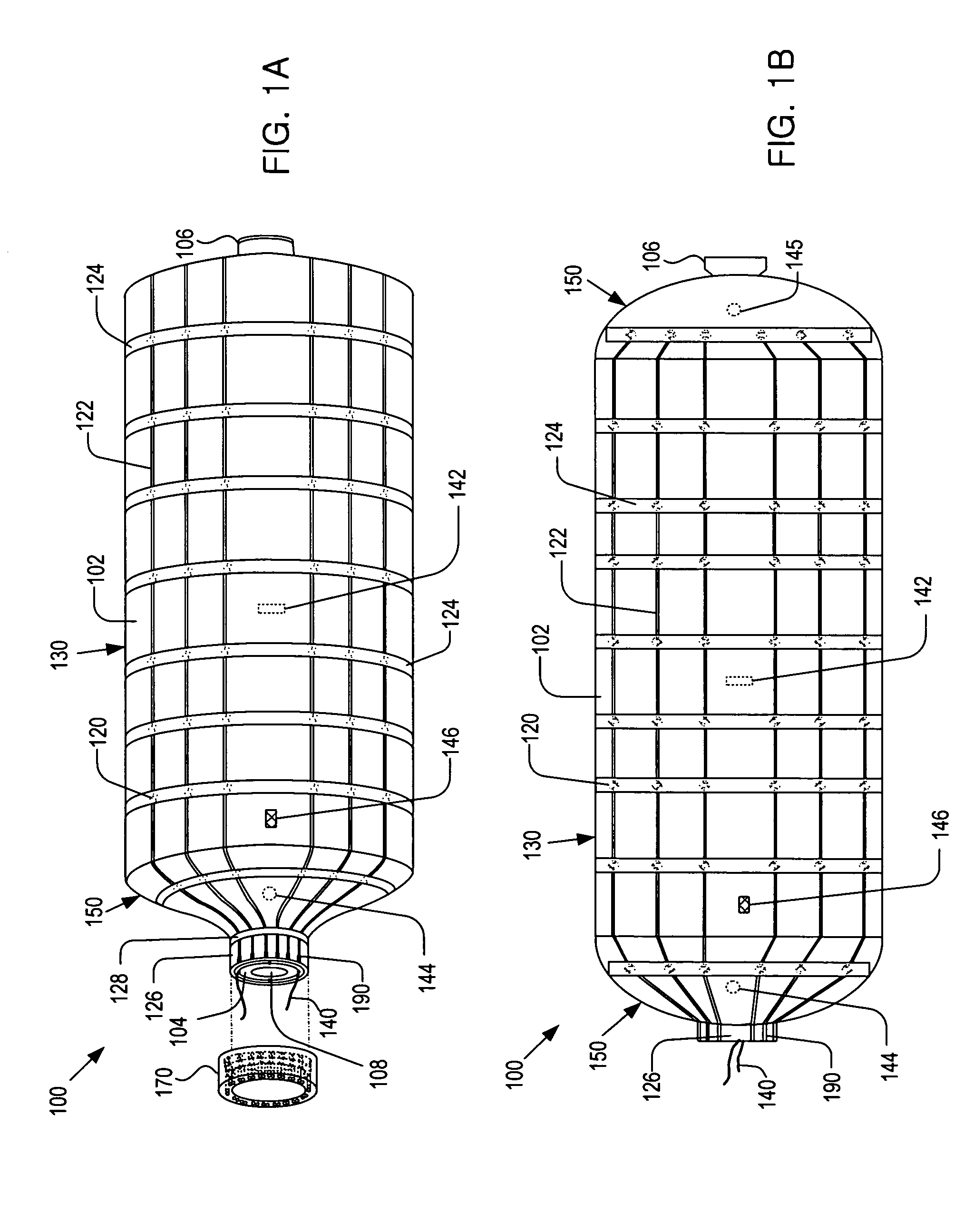
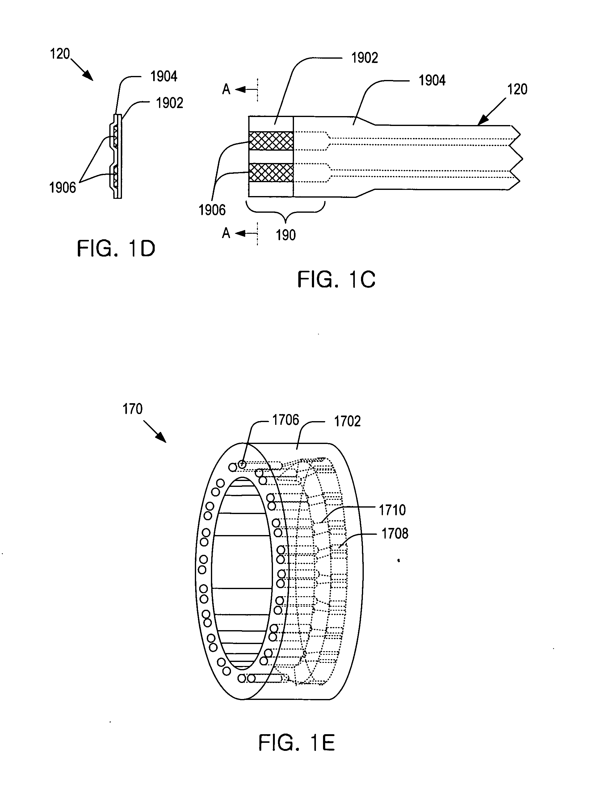
[0022]Briefly, the present invention provides a gas tank having diagnostic network patch (DNP) devices to monitor the health conditions of the tank. An interrogation system associated with the DNP devices or transducers establishes signal paths between the devices to form a communication network, where acoustic waves or impulses (such as, Lamb waves) travel through the signal paths. The signals transmitted through the paths are received by some of the DNP devices and the received data are analyzed by the interrogation system to determine the structural conditions of the tank...


PUM

PropertyMeasurementUnit
permeationaaaaaaaaaa
shapeaaaaaaaaaa
temperatureaaaaaaaaaa

Abstract

A tank having a system for monitoring the structural conditions of the tank. The tank includes: an inner liner adapted to contain a gas thereinside and to prevent permeation of the gas therethrough; a shell surrounding the inner liner; and a plurality of diagnostic network patches (DNP) attached to the outside surface of the shell. Each DNP is able to operate as a transmitter patch or a sensor patch, where the transmitter patch is able to transmit a diagnostic signal and the sensor patch is able to receive the diagnostic signal. The diagnostic signal received by the DNP is analyzed to monitor the structural conditions of the tank.

Description

CROSS REFERENCE TO RELATED APPLICATIONS[0001]This application is a continuation-in-part of U.S. patent application Ser. No. 11 / 880,043, filed on Jul. 18, 2007, which is a continuation-in-part of U.S. application Ser. No. 11 / 502,127, filed on Aug. 9, 2006, now U.S. Pat. No. 7,325,456, which is a continuation-in-part of U.S. patent application Ser. No. 10 / 942,366, filed on Sep. 16, 2004, now U.S. Pat. No. 7,117,742, which claims the benefit of U.S. Provisional Application No. 60 / 505,120, filed on Sep. 22, 2003. This application claims the benefit of U.S. Provisional Application No. 60 / 903,385, entitled “Smart vehicle's fuel storage tank,” filed on Feb. 26, 2007, which is hereby incorporated herein by reference in its entirety.BACKGROUND OF THE INVENTION[0002]The present invention relates to storage devices and, more particularly to, gas tanks having systems for monitoring structural conditions thereof.[0003]It is of prime importance in designing a gas tank that the gas tank be capable...

Claims


Application Information

Patent Timeline
Patent Type & Authority Applications(United States)
IPC IPC(8): G01N29/00
CPCF17C13/02F17C2270/0171F17C2201/032F17C2201/035F17C2201/054F17C2203/0604F17C2203/0621F17C2203/0636F17C2203/066F17C2203/0663F17C2205/0142F17C2205/0196F17C2205/0326F17C2205/0332F17C2205/0397F17C2223/0123F17C2223/033F17C2223/035F17C2250/032F17C2250/034F17C2250/043F17C2250/0439F17C2250/0465F17C2250/0469F17C2250/0491F17C2250/0495F17C2250/072F17C2260/015F17C2201/0109
Inventor KIM, HYEUNG-YUN
Owner KIM HYEUNG YUN
Why Eureka
Try Eureka