Apparatus and Process For Cooling Hot Gas

Active Publication Date: 2008-06-26
SHELL USA INC
View PDF9 Cites 8 Cited by
  • Summary
  • Abstract
  • Description
  • Claims
  • Application Information

AI Technical Summary

Benefits of technology

[0011]It is therefore an object of the present invention to provide a heat exchanger apparatus comprising a specific inlet section for bette

Problems solved by technology

Furthermore the annular gaps as described earlier for the prior art designs

Method used


Image

  • Apparatus and Process For Cooling Hot Gas
  • Apparatus and Process For Cooling Hot Gas
  • Apparatus and Process For Cooling Hot Gas

Examples


Example

DETAILED DESCRIPTION OF THE DRAWINGS

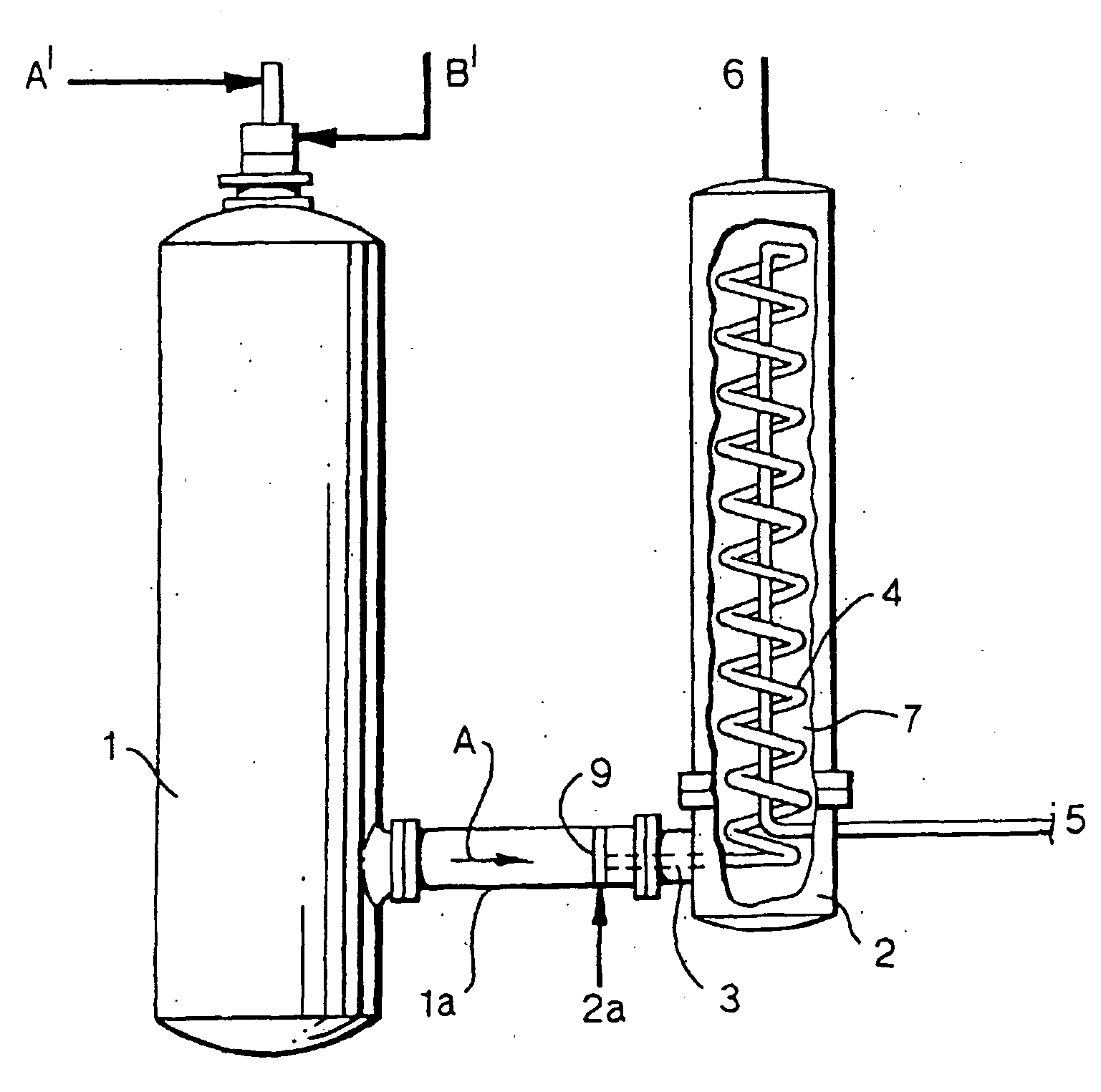
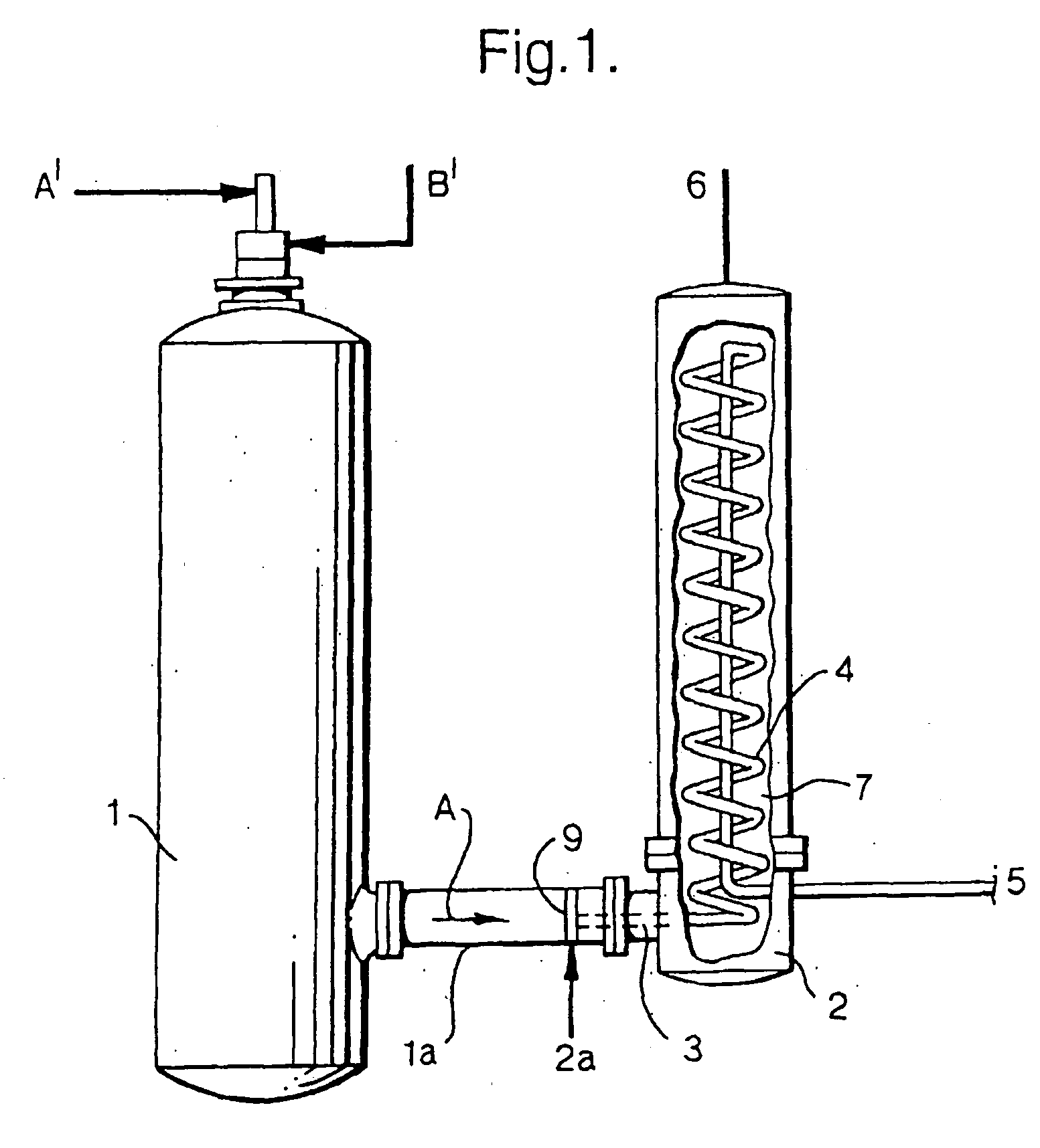
[0025]Referring to FIG. 1 a reactor 1 is shown for producing product gas e.g. by partial oxidation of hydrocarbon-containing fuel.

[0026]The product gas is supplied to a heat exchanger 2 and is further treated in any suitable manner after heat exchange. Such partial oxidation processes and appropriate process conditions are generally known to those skilled in the art and will therefore not be described in detail.

[0027]Generally, it can be said that (hydro)carbon-containing fuel A′ (optionally with a moderator) and an oxidizer B′ (optionally with a moderator) are supplied to the reactor 1 wherein raw hot synthesis gas is produced under appropriate process conditions.

[0028]The raw hot synthesis gas is supplied from the reactor 1 via a duct 1a to the gas inlet 9 of the heat exchanger vessel 2 located next to the reactor.

[0029]The arrows A represent the synthesis gas flow direction.

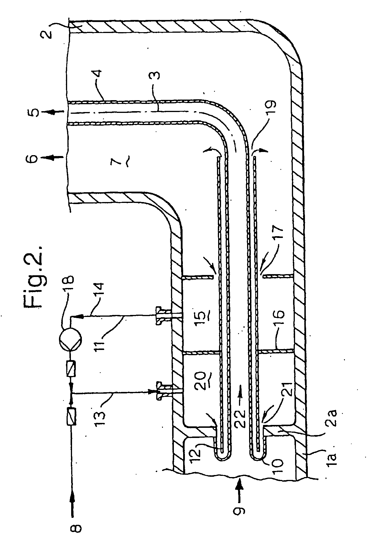
[0030]The mechanical connections of reactor and duct on the one side an...


PUM


Abstract

Process to cool hot gas by passing the hot gas through a tube having a main tubular part and an upstream tubular part, wherein (i) the exterior of main tubular part is cooled by an evaporating liquid cooling medium flowing freely around said tube, (ii) the upstream tubular part is cooled by passing fresh liquid cooling medium and a defined part of the liquid cooling medium of activity (i) along the exterior of the upstream end of the tube and (iii) wherein the mixture of fresh cooling medium and the defined part of the liquid medium after being used to cool the upstream tubular part is used in activity (i) as cooling medium.

Description

FIELD OF THE INVENTION[0001]The invention relates to an apparatus and process for cooling hot gas which apparatus comprises a vessel provided with one or more heat exchanging tubes, the hot gas flowing through the said tube(s) and a cooling medium (e.g. water) flowing round the said tubes and the tubes being mounted at least at one end in a tube plate.BACKGROUND OF THE INVENTION[0002]Such heat exchange devices are used on a large scale in many branches of industry, e.g. in the petroleum industry for cooling products obtained from hydrocrackers and reactors for partial oxidation of (hydro)carbon-containing fuels such as oil and coal and the like.[0003]When for cooling purposes the hot gases are passed through tubes which are cooled with a cooling medium on the outside, the walls of the tubes acquire a high temperature owing to transfer of heat from the hot gases to the tube metal which heat is further transmitted to the cooling medium. Advantageously, for reasons of space saving heli...

Claims


Application Information

Patent Timeline
IPC IPC(8): F28D7/02F28F9/02
CPCF28D7/024F28F9/0229F28D2021/0075F28D7/00F28D7/02F28F9/02
Inventor FRIESE, ECKHARD HEINRICH ERICH OTTOVON KOSSAK-GLOWCZEWSKI, THOMAS PAULPAPENDICK, JOACHIMVAN DER PLAS, TYCHO AGIENSCHMITZ-GOEB, MANFRED HEINRICHVOETEN, EDWIN BERNARDUS WILHELMUS GERARDUS
Owner SHELL USA INC
Why Eureka
Try Eureka